5-2
5
CONTROL COMMANDS
The transceiver’s operating frequency, mode can be remotely controlled using a PC.
The Icom Communications Interface V (CI-V) controls the transceiver.
Set the “CI-V address,” “CI-V Baud Rate,” and “CI-V transceive” function in the Initial set mode.
(Refer to the basic manual.)
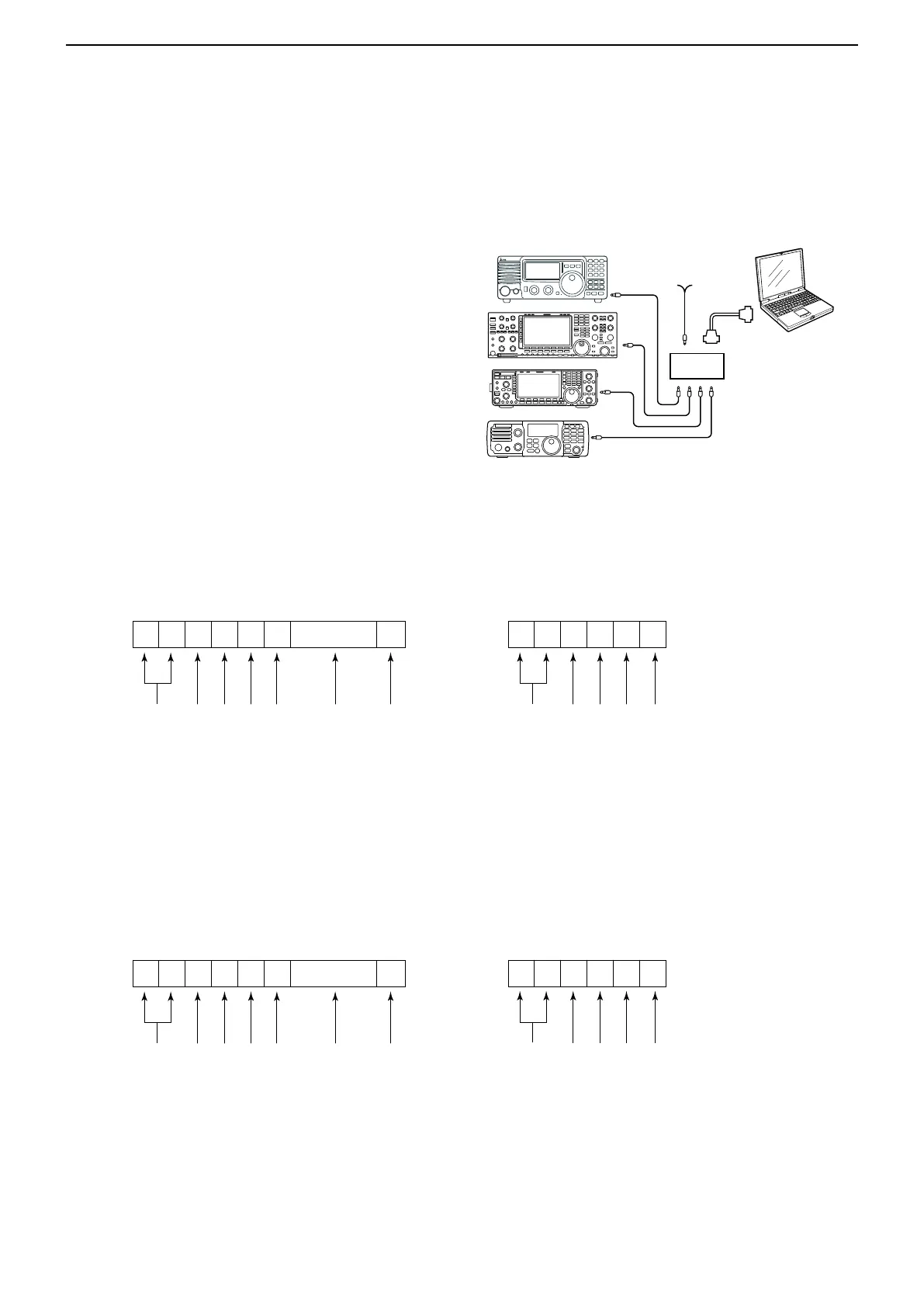
When you remotely control the transceiver, use a CT-
17 (discontinued product) or
cable (User supplied) to connect the PC.
The transceiver can be connected through an optional
CT-17 to a PC equipped with an RS-232C port.
D Data format
The CI-V system can be written using the following
command numbers. A data area or sub command is
added for some commands.
CONTROLLER TO IC-718
FE
FE
FE 5E E0 Cn Sc Data area FD
Preamble code (fixed)
Transceiver’s default address
Controller’s default address
Command number
(see table on the next page)
Sub command number
(see table at right)
BCD code data for frequency or
memory number entry
End of message code (fixed)
OK MESSAGE TO CONTROLLER
FE FE E0 5E FB FD
Preamble code (fixed)
Controller’s default address
Transceiver’s default address
OK code (fixed)
End of message code (fixed)
NG MESSAGE TO CONTROLLER
FE FE E0 5E FA FD
Preamble code (fixed)
Controller’s default address
Transceiver’s default address
NG code (fixed)
End of message code (fixed)
IC-718 TO CONTROLLER
FE E0 5E Cn Sc Data area FD
Preamble code (fixed)
Controller’s default address
Transceiver’s default address
Command number
(see table at right)
Sub command number
(see table at right)
BCD code data for frequency or
memory number entry
End of message code (fixed)
1
2 3 4 5 6 7
1 2 3 4 5 6 7
9–15 V DC
PC
CT-17
Mini-plug cable
IC-718
MODE
TUNER
TS
FILTER
V/M
A/B
SPLIT
M-CL
SCAN
SET
ATT
P
.
AMP
COMP
VOX
MNF
RIT
1
2
3
4
5 6
7
8
0
50
28
1814
10
21
24
=
7
3.5
1.8
F-INP
M-CH/RIT
ENT
BAND
GENE
9
.
AGC
MW
ANF
METER
NR
NB

 Loading...


