4 - 1
SECTION 4 ADJUSTMENT PROCEDURE
4-1 PREPARATION
¤ REQUIRED EQUIPMENTS
EQUIPMENT SPECIFICATION EQUIPMENT SPECIFICATION
Spectrum analyzer
Frequency range : At least 90 MHz
Bandwidth : 100 kHz or more
Digital multimeter
Input impedance : 50 k
Ω
/DC or more
Measuring range : Voltage: 0.1–10V
Current: 5A/30A
RF power
(terminated type)
Measuring range : 10–300 W
Frequency range : 1.8–100 MHz
Impedance : 50
Ω
SWR : Less than 1.2 : 1
Standard Signal
Generator (SSG)
Frequency range : 0.1–100 MHz
Output level : 0.1 µV to 32 mV
(–127 to –17 dBm)
Frequency Counter
Frequency range : 0.1–100 MHz
Frequency accuracy :
±0.5 ppm or better
Input level : Less than 1 mW
AC Millivoltmeter Measuring range : 10 mV to 10 V
Modulation
Analyzer
Frequency range : 30–300 MHz
Measuring range : 0 to ±10 kHz
External Speaker
Input impedance : 8
Ω
Capacity : More than 5 W
Audio Generator
Frequency range : 300–3000 Hz
Output level : 1–500 mV
Attenuator
Power attenuation : 50 or 60 dB
Capacity : More than 200 W
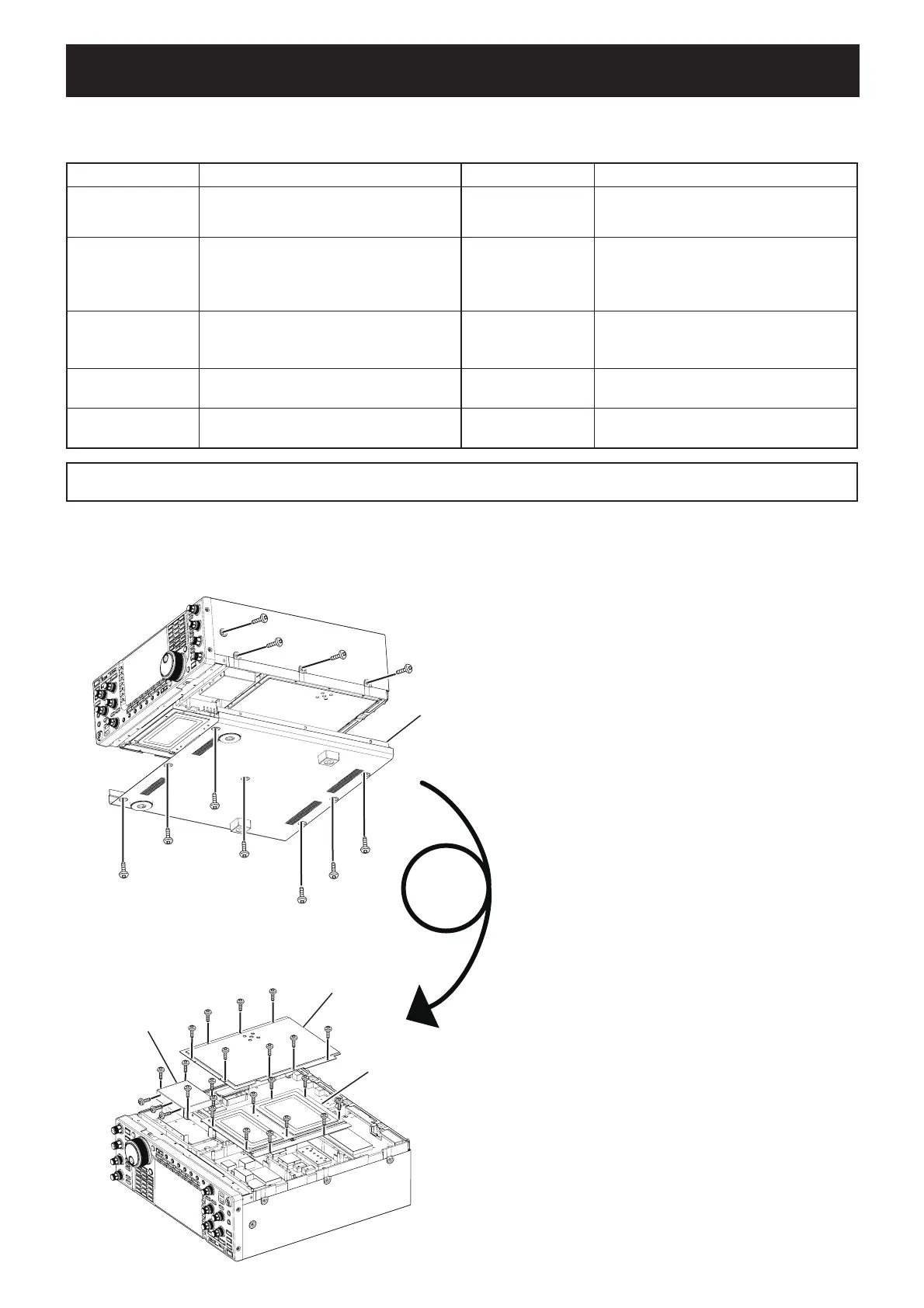
¤ EXPOSING UNITS
OSC UNIT cover
RF UNIT cover
Bottom cover
PLL/SCOPE UNITs cover
1) Remove 8 screws from the both sides.
2) Remove 7 screws from the bottom, then remove the
bottom cover.
3) Turn over the transceiver.
4) Remove 8 screws from the RF UNIT cover, 10 screws
from the PLL/SCOPE UNITs cover and 10 screws
from the OSC UNIT cover, then remove those covers.
CAUTION: The transceiver weighs approx. 22.5 kg (50 lb). Always have two people available to carry, lift or turn over the transceiver.
CAUTION!: BACK UP originally programmed contents (Memory channels, Common settings, etc.) in the transceiver before
starting adjustment. When all adjustments are completed, these contents in the transceiver will be cleared.

 Loading...


