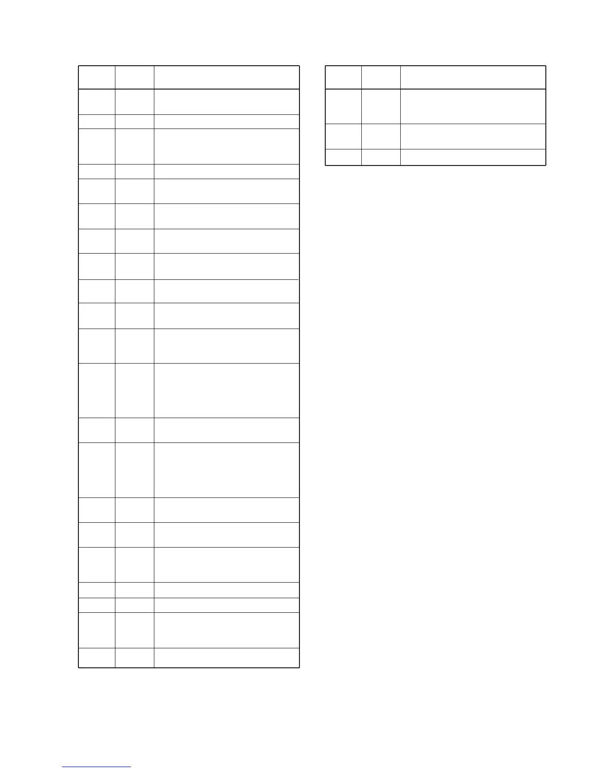
Description
Input ports for the key matrix.
Input port for the CPU reset signal.
Outputs control signal for the power
supply circuit.
High: Power is ON.
Outputs beep audio signals.
Outputs clock signal to the EEPROM
(FRONT unit; IC4, pin 6).
Outputs data signal to the EEPROM
(FRONT unit; IC4, pin 5).
Outputs chip select signal to the EEP-
ROM (FRONT unit; IC4, pin 1).
Input port for the [DIAL] control signal.
Outputs control signal to the expander
IC (FRONT unit; IC5, pin 15).
Outputs strobe signals to the
expander IC (FRONT unit; IC5, pin 1).
Outputs chip select signal to the elec-
tric volume (MAIN unit; IC13).
Low: While volume is controlled.
Outputs serial clock to the PLL IC
(MAIN unit; IC2, pin 3), the expander
IC (FRONT unit; IC5, pin 3) and the
electric volume (MAIN unit; IC13, pin
8).
Input port for the data signal from the
EEPROM (FRONT unit; IC4, pin 2).
Outputs serial data to the PLL IC
(MAIN unit; IC2, pin 4), the expander
IC (FRONT unit; IC5, pin 2) and the
electric volume (MAIN unit; IC13, pin
9).
Outputs strobe signals to the PLL IC
(MAIN unit; IC2, pin 5).
Outputs 2nd IF filter’s select signal.
High: While wide is selected.
Input port for the unlock signal from
the PLL IC (MAIN unit; IC2, pin 11).
Low: PLL is unlocked.
Input port for the cloning signal.
Output port for the cloning signal.
Input port for the POWER switch.
Low: While POWER switch is
pushed
Input port for the squelch signal.
Port
name
KR4
RESET
PSWC
BEEP
ECK
ESO
ECS
DLA,
DLB
OE
EXSTB
VCS
SCK
ESI
SO
PLSTB
FISW
UNLK
CLIN
CLO
PSW
SQLI
Pin
number
1, 2, 3,
5, 8, 12
9
10
11
13
14
15
16,
17
18
19
20
21
22
23
24
25
69
70
71
72
74
3 - 6
Pin
number
76
77
78–80
Port
name
HANG
PTT
KR1–KR2
Description
Input port for the microphone hanger
detection signal.
Low: Microphone on hook.
Input port for the PTT switch.
High: While PTT switch is pushed.
Input ports for the key matrix.
3-5-2 CPU (FRONT unit; IC1)