EasyManua.ls Logo

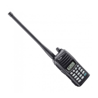
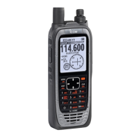
Icom IC-A14

Icom IC-A14
28 pages
To Next Page IconTo Next Page
Loading...
S-14417XZ-C1
Jan. 2008
VHF AIR BAND TRANSCEIVER

Other manuals for Icom IC-A14

Questions and Answers:

Icom IC-A14 Specifications

General IconGeneral
Power Supply Requirement7.2 V DC
ModeSimplex
TypeAviation Transceiver
Frequency Range118.000 - 136.975 MHz
Channel Capacity200 Channels
Power Output5 W
Battery LifeApprox. 8 hours (with standard battery)
Channel Spacing25 kHz
Current Drain (at 7.2 V DC)1.5 A (max)
Modulation SystemAM
Spurious EmissionsLess than –60dBc
Audio Output Power500 mW (at 10% distortion)
Adjacent Channel Selectivity70 dB
Spurious Response Rejection70 dB

Summary

Specifications

Inside Views

PA Unit Views

Shows the top and bottom views of the Power Amplifier unit components.

Main Unit Views

Displays the top and bottom views of the Main Unit components.

Disassembly Instructions

Front Panel Removal

Step-by-step guide for safely removing the front panel assembly.

Main Unit Removal

Instructions for detaching the main circuit board unit from the chassis.

PA Unit Removal

Procedure for safely disassembling the Power Amplifier unit.

Circuit Description

Receiver Circuitry

Details the signal path and components for receiving radio signals.

Transmitter Circuitry

Explains the circuitry responsible for transmitting radio signals.

Frequency Synthesizer Circuits

Describes the VCO and PLL circuits for frequency generation.

Port Allocations

Lists and explains the function of each CPU port.

Voltage Block Diagram

Illustrates the power distribution and voltage regulation.

Parts List

Mechanical Parts

Chassis Mechanical Parts

Lists mechanical components associated with the transceiver's chassis.

PA Unit Mechanical Parts

Lists mechanical components specific to the Power Amplifier unit.

ANT Unit Mechanical Parts

Lists mechanical components for the Antenna unit.

DC Unit Mechanical Parts

Lists mechanical components for the DC power unit.

Accessories List

Lists optional accessories and included items for the transceiver.

Main Unit Mechanical Parts

Lists mechanical components specific to the Main Unit.

Board Layouts

Main Unit Top View Layout

Diagram showing component placement on the top of the main board.

PA Unit Top View Layout

Diagram showing component placement on the top of the PA unit board.

ANT Unit Top View Layout

Diagram showing component placement on the top of the antenna unit board.

DC Unit Top View Layout

Diagram showing component placement on the top of the DC unit board.

Block Diagram

Voltage Diagram

Main Unit Voltage Diagram (Left Side)

Detailed voltage schematic for the left section of the main unit.

Main Unit Voltage Diagram (Center)

Detailed voltage schematic for the center section of the main unit.

Main Unit Voltage Diagram (Right Side)

Detailed voltage schematic for the right section of the main unit.

Related product manuals