(Replacement page)
4-1a
SECTION 4 ADJUSTMENT PROCEDURE
March 2019
4-1 PREPARATION
■ REQUIRED EQUIPMENT
EQUIPMENT SPECIFICATIONS EQUIPMENT SPECIFICATIONS
DC power supply
Output voltage: 11 V
Current capacity: 5 A or more
Programming software
CS-A25 Programming software
(Revision 1.0 or later)
Battery pack
BP-288 (Fully charged)
Programming cable OPC-478UC
RF power meter
(50 Ω terminated)
Measuring range: 0.1~5 W
Frequency range: 100~300 MHz
SWR: Less than 1.2 : 1
Standard signal
generator (SSG)
Frequency range: 0.1~300 MHz
Output level: −20 dBμ to 90 dBμ
(−127 to −17 dBm)
Frequency counter
Frequency range: 0.1~300 MHz
Frequency accuracy: ±1 ppm or better
Audio generator (AG)
Frequency range: 300~3000 Hz
Output level: 1~500 mV
Modulation Analyzer
Frequency range: 30~300 MHz
Measuring range: 0~100%
JIG cable See the illustration below.
AC millivoltmeter Measuring range: 10 mV to 10 V
Attenuator
Power attenuation: 30~40 dB
Capacity: More than 10 W
VOR tester
Frequency range: 108~118 MHz
Output level: −20 dBμ to 90 dBμ
(−127 to −17 dBm)
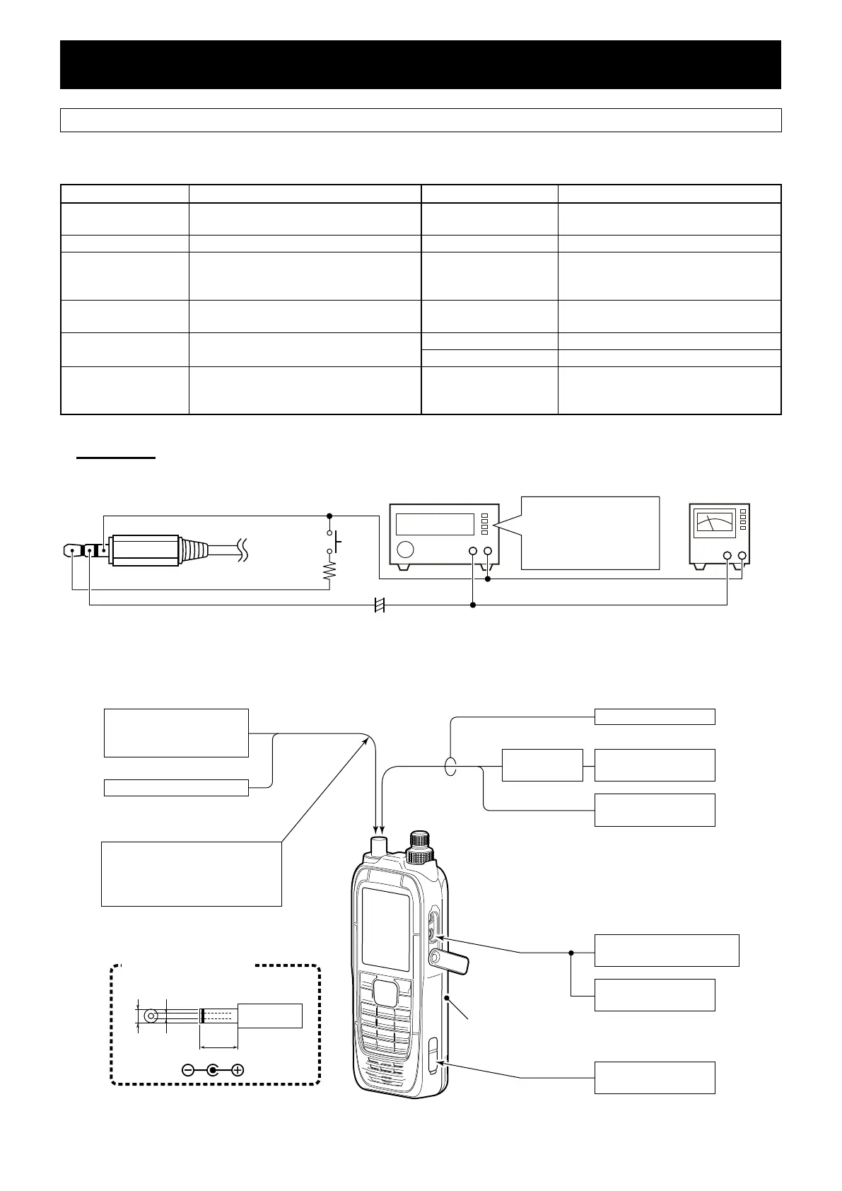
■ JIG CABLE
3-conductor 2.5 mm
(d) mm plug
(MIC)
(PTT)
(GND)
33 kΩ
+ −
AC MILLIVOLTMETER
(10 mV to 10 V)
AUDIO GENERATOR
(300~3000 Hz/1~500 mV)
+ −
PTT
SETTING:
Frequency: 1 kHz
Level: 200/20 mV
Waveform: Sine wave
4.7 µF
+
■ CONNECTIONS
Standard signal generator
−20 dBμ to 90 dBμ
(−127 dBm to −17 dBm)
RF power meter
0.1~5 W
Frequency counter
AC millivoltmeter
10 mV to 10 V
VOR Tester
CAUTION!
DO NOT transmit while the SSG
or VOR tester is connected to the
antenna connector.
Battery pack
(Fully charged BP-288)
To [MIC]
Loose
coupling
To [DC 11V]
Modulation Analyzer
0~100%
Attenuator
30~40 dB
DC power supply
11 V/5 A or more
Audio generator
300~3000 Hz/1~500 mV
Used DC power plug
(for power supply connection)
Ø3.4
Ø1.35
(Unit: mm)9.5
The underlined parts have been updated from the previous version of the addendum, or the original page.
 Loading...