(Amended page)
March 2019
The underlined parts have been updated from the previous version of the addendum, or the original page.
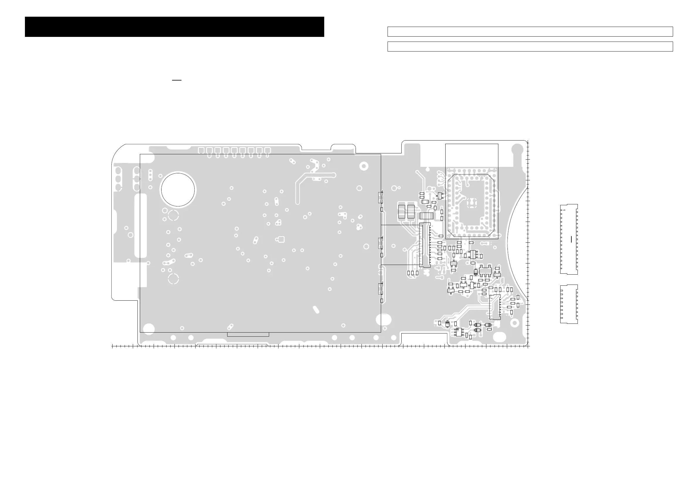
The actual configuration of the PC board can be seen by viewing the top and bottom BOARD LAYOUT pages together.
See the PARTS LIST H/V location on the PARTS LIST for location details.
BOARD LAYOUTS
7-1a
C1
C2
C16
C155
C156
C157
C158
C159
C161
C643
C648
C649
C662
C663
C664
C666
C667
C693
C695
C696
C703
C704
C705
C708
D1
D2
D4
D5
D6
D46
4SD3SD2SD
EP10
EP11
EP12
EP13
EP14
EP16
EP19
IC1
IC30
IC39
J2
J4
Q5
Q17
Q31
Q32
Q33
Q34
R145
R146
R147
R148
R151
R152
R863
R866
R876
R878
R917
R920
R947
R949
R952
R963
R1053
R1054
R1055
R1056
R1060
R1063
R1064
R1065
R1066
R1067
R1068
R1069
R1070
R1071
R1072
R1073
R1077
GND
BT SW
BTRXD
CPU3V
BT RST
BTTXD
RESET
FINED
G-TXD
G-RXD
VCC
PCON
B-8813
H0H5H10H15H20H25H30
H35H40H45
V0 V5 V10 V15 V20 V25 V30 V35 V40 V45 V50 V55 V60 V65 V70 V75 V80 V85 V90 V95 V100
R26R25
GND
GND
KS3
KS1
KR4
KR2
KR0
GND
KEYLIGHT
PWRBTN
KS2
KS0
KR3
KR1
GND
J2
J4
J2
NC
CPU3V
CPU3V
GND
LCDA0
CPU3V
LCDSCL
LCDSDA
CPU3V
CPU3V
NC
NC
NC
NC
GND
GND
LCDCSB
CPU3V
LCDRSTB
LCDSDA
LCDSDA
CPU3V
CPU3V
NC
NC
J4
CPU3V
• LOGIC UNIT (B-8813 for #11, #12, #21, #22, and #31: TOP VIEW)
 Loading...