SECTION 3 DISASSEMBLY INSTRUCTION
3-1
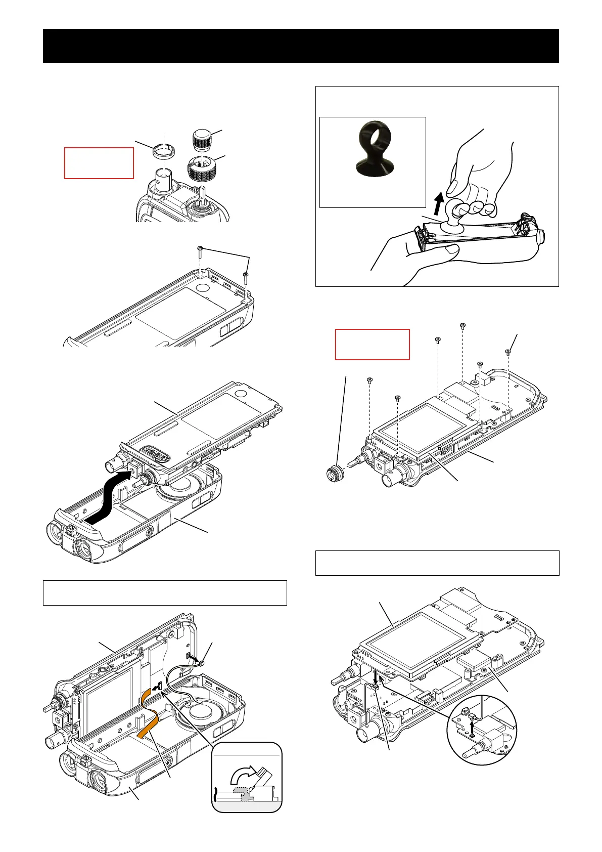
1. REMOVING THE LOGIC/-1 UNIT
Remove 2 dial knobs and antenna nut from the 1)
front panel.
Antenna nut
Inner dial
Outer dial
Remove with;
“ICOM Driver (K)”
(8960000112)
Remove 2 screws from the bottom of chassis.2)
Separate the chassis from the front panel, then 3)
disconnect flat and speaker cables.
BE CAREFUL about the flat and speaker cables when
separating the chassis from the front panel.
Front panel
Flat cable
Speaker cable
Chassis
FLAT CABLE
Lift up
flat cable
Suction lifter
For easy separation of the CHASSIS
Use a suction lifter to lift the bottom of the CHASSIS up.
Suction lifter
• Part name: EA950R-2
• Manufacture: ESCO CO.LTD
Remove dial nut and 6 screws from the LOGIC/-1 4)
UNIT.
LOGIC/-1 UNIT
Chassis
Screws×6
Dial nut
Remove with;
“ICOM Driver (AG)”
(8960000560)
Separate the LOGIC/-1 UNIT from the MAIN/-1 5)
UNIT, and then disconnect the coaxial cable from
the LOGIC-A UNIT.
BE CAREFUL about the coaxial cable when separating the
LOGIC/-1 UNIT from the MAIN/-1 UNIT.
Coaxial cable
LOGIC/-1 UNIT
MAIN/-1
UNIT
 Loading...