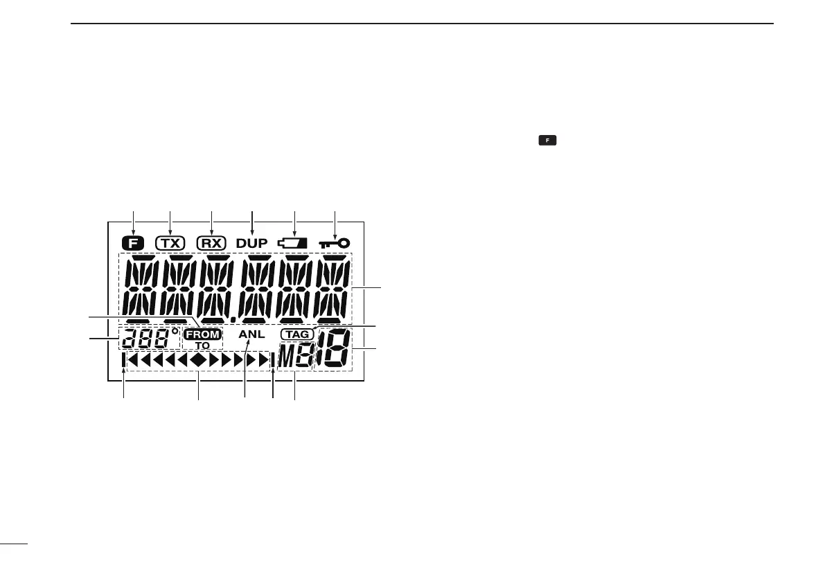
EasyManuals Logo

Icom IC-A6 User Manual

Icom IC-A6
44 pages
To Next Page IconTo Next Page
To Previous Page IconTo Previous Page
Page #10 background imageLoading...
Page #10 background image
6
2
PANEL DESCRIPTION
Function display
q FUNCTION INDICATOR (p. 3)
Appears when is pushed.
w TX INDICATOR (p. 9)
Appears while transmitting.
e RX INDICATOR (p. 9)
Appears when receiving a signal, or when the squelch
opens.
r DUPLEX INDICATOR (IC-A24 only) (p. 24)
➥“DUP” appears when the duplex function is activated in
the NAV mode.
➥“DUP” blinks while setting the duplex frequency.
t LOW BATTERY INDICATOR (p. 10)
Appears when the battery is nearing exhaustion. The
attached battery pack requires recharging.
Appears and flashes when battery replacement is nec-
essary.
y LOCK INDICATOR (p. 11)
Appears while the lock function is in use.
i
qw erty
o
!0
!1!1 !2!3
!4
u
!5

Table of Contents

Other manuals for Icom IC-A6

Questions and Answers:

Question and Answer IconNeed help?

Do you have a question about the Icom IC-A6 and is the answer not in the manual?

Icom IC-A6 Specifications

General IconGeneral
Frequency Range118.000–136.975 MHz
Channel Spacing25 kHz
Antenna Impedance50Ω
Power Supply Requirement7.2 V DC
WaterproofNo
Channels200 channels
Current Drain1.5 A (at max output)
RF Output Power5 W (PEP)
ModulationAM
Battery Life15 hours
Weight430g
Dimensions54 x 129.3 x 35.5 mm

Related product manuals