20
6
VOR NAVIGATION (IC-A24 ONLY)
Flying to a VOR station
■
The IC-A24 shows the deviation from a VOR station.
q Select a VOR station on your aeronautical chart and push
the keypad or rotate [DIAL] to set the frequency of the
station.
• The course indicator indicates where you are located on a ra-
dial from the VOR station.
• The course indicator shows ‘- -’ when either aircraft is too far
away from the VOR station or the frequency is not set correctly
at the VOR station.
w Select the ‘TO’ ag when ying to the VOR station, or se-
lect the ‘FROM’ ag when ying away from the VOR sta-
tion.
• Push , then push [2•TO] to select ‘TO’.
• Push , then push [3•FROM] to select ‘FROM’.
e Push , then push [4•CDI] to select the CDI (Course
Deviation Indicator) mode.
• The course indicator shows ‘OF’ when the desired VOR signal
cannot be received.
NOTE: When the CDI mode is selected, the operating fre-
quency cannot be changed. To set the operating fre-
quency, select the DVOR mode in advance.
r The course deviation needle appears when your aircraft
is off course from the VOR station.
• ‘Ω’ or ‘≈’ appears to indicate your aircraft is off course to the
right or left, respectively. Correct your course until ‘Ω’ or ‘≈’ dis-
appears. Each arrow represents a two-degree deviation.
t Push , then push [1•DVOR] to exit the CDI mode.
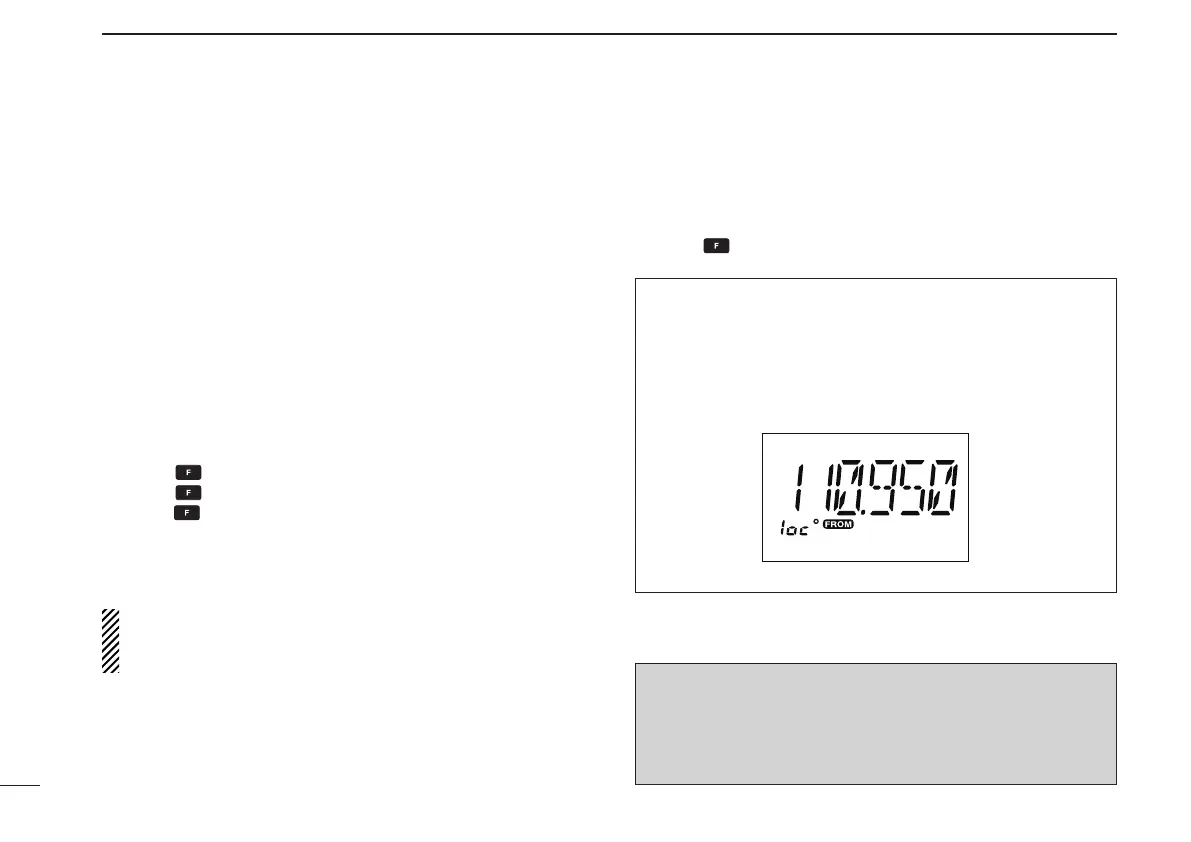
VOR INDICATOR NOTE
‘loc’ appears on the function display as shown below when
a localizer signal is received.
However, the function display does not indicate additional
information about the localizer signal.
NOTE: For only the U.S.A. version
IC-A24’s VOR and CDI Navigation features are supple-
mental aids to navigation only, and are not intended to be
a substitute for accurate (primary) VOR/CDI or landing
service equipment.