21
6
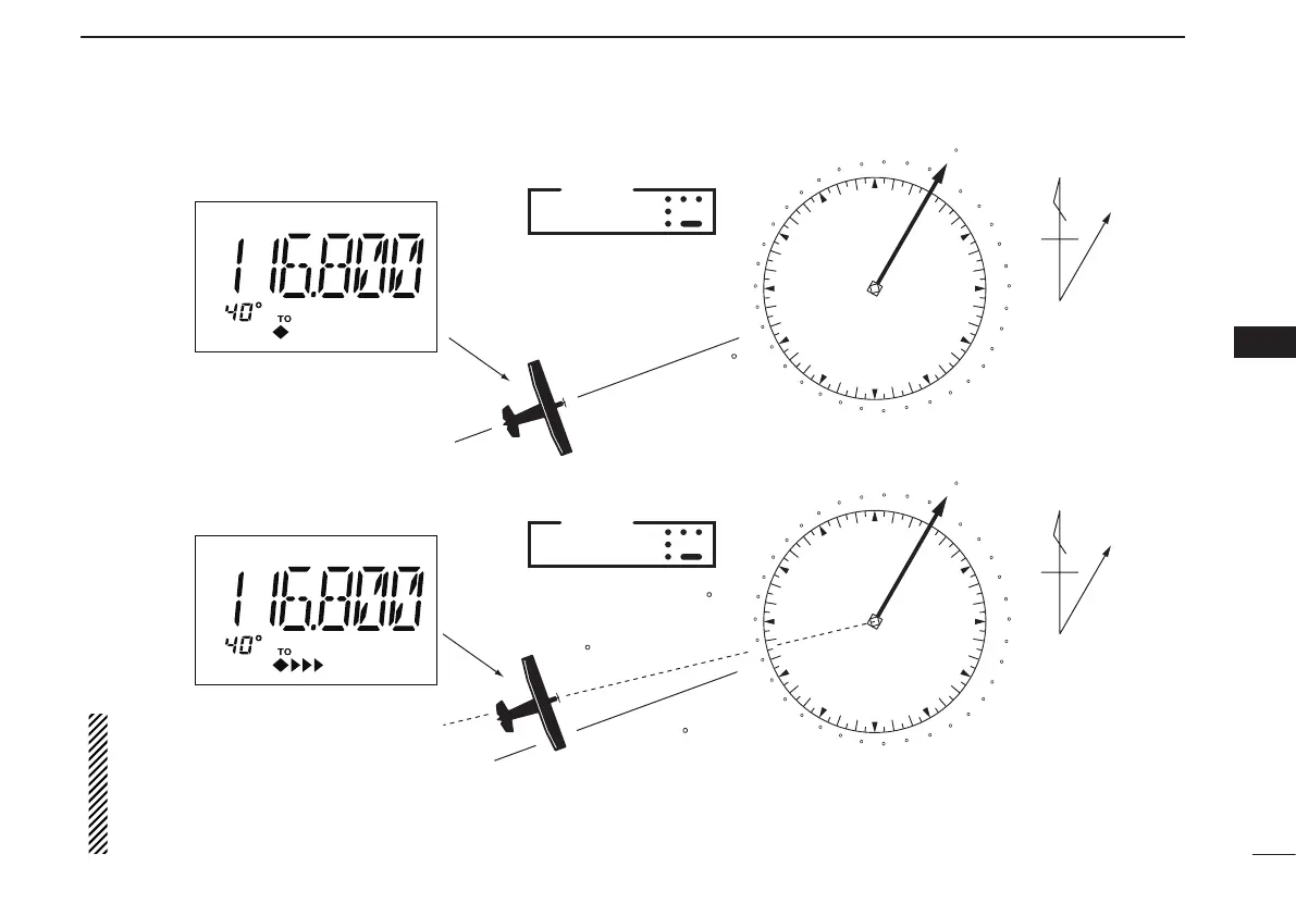
VOR NAVIGATION (IC-A24 ONLY)
VOR
station
0
10
20
30
40
50
60
70
80
90
100
110
120
130
140
150
160
170
180
190
200
210
220
230
240
250
260
270
280
290
300
310
320
330
340
350
N
Magnetic
north
Desired course
Aircraft heading 40
123.65
VORTAC
SEATTLE
116.8 Ch 115 SEA
THE AIRCRAFT IS ON COURSE
VOR
station
0
10
20
30
40
50
60
70
80
90
100
110
120
130
140
150
160
170
180
190
200
210
220
230
240
250
260
270
280
290
300
310
320
330
340
350
N
Magnetic
north
Aircraft should be
heading 40
Aircraft heading 46
(6 off course)
Flown course
123.65
VORTAC
SEATTLE
116.8 Ch 115 SEA
THE AIRCRAFT IS OFF COURSE
NOTE: The course deviation indica-
tor appears when the aircraft is off
course. In this example, the aircraft
is 6 degrees off course to the left.
The pilot must turn more than 6 de-
grees right to get back on course.
2
3
1
4
5
6
7
9
10
8
12
13
11
14