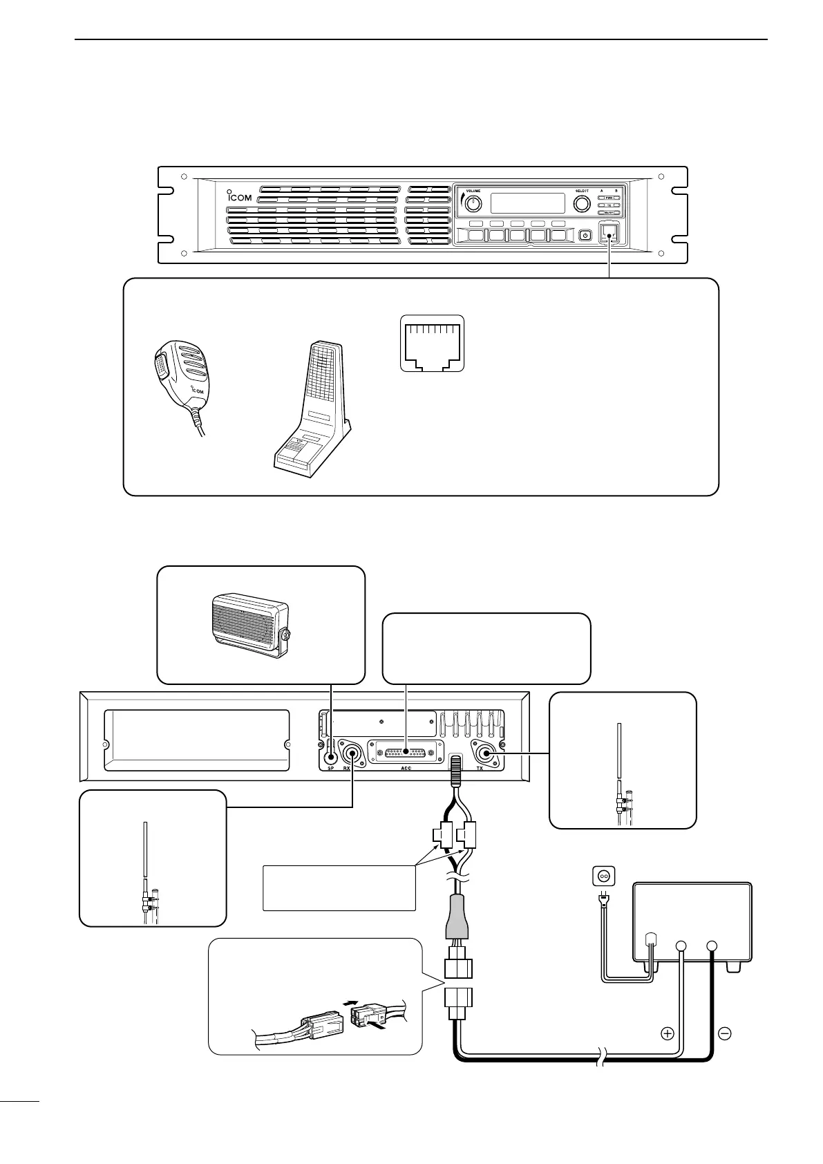
■ Front panel connection
P
0
P
1
P
2
P
3
P
4
SM-25 DESKTOP
MICROPHONE
(optional)
MICROPHONE CONNECTOR (Front panel view)
HM-152 HAND
MICROPHONE
(optional)
q
i
CAUTION: DO NOT short pin 1 to ground as this can
damage the internal 8 V regulator. DC voltage is applied
to pin 1 for microphone operation. Only Icom micro-
phones are recommended.
q +8 V DC output (Max. 15 mA)
w Output port for PC programming
e NC
r M PTT (Input port for TX control)
t Microphone ground
y Microphone input
u Ground
i Input port for PC programming
■ Rear panel connection
ACC CONNECTOR (p. 3)
Used for external equipment control.
[RX ANT] (p. 4)
[TX ANT] (p. 4)
SP-22 EXTERNAL SPEAKER
Connect a 4 ˘ external speaker.
Black
Red
20 A
fuses
DC power supply
AC outlet
AC cable
Supplied
DC power cable
13.6 V; at least 20 A
Black
_
Red
+
R W ARNING! NEVER
remove the fuse-holder from
the DC power receptacle.
q Push
w
R
WARNING! When you discon-
nect the DC power cable, take care
to not damage of your fingernail.
5
2
INSTALLATION AND CONNECTIONS

 Loading...


