EasyManua.ls Logo

Icom IC-FR3000 Service Manual

Icom IC-FR3000
136 pages
To Next Page IconTo Next Page
Page #1 background imageLoading...
Page #1 background image
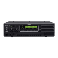
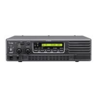
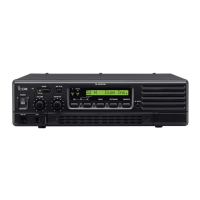
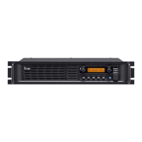
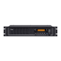
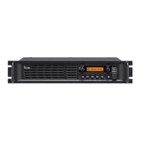
VHF FM REPEATER
iC-fr3000
iC-fr3100

Other manuals for Icom IC-FR3000

Questions and Answers:

Icom IC-FR3000 Specifications

General IconGeneral
Number of Channels1000
Power Output50W
Operating Temperature Range-30°C to +60°C
Frequency Range136-174 MHz, 400-470 MHz
Modulation16K0F3E
Power Supply13.8 V DC ±15%
Channel Spacing12.5 kHz / 25 kHz

Summary

Introduction to the Service Manual

Safety and Handling Precautions

DANGER Warnings

Critical warnings for operating the repeater to prevent damage or injury.

Repair Notes

Essential guidelines for safe and effective repair procedures.

Section 1 Specifications

General Specifications

Covers frequency, channels, power, temperature, and dimensions.

Transmitter Specifications

Details output power, modulation, and emissions.

Receiver Specifications

Outlines receiving system, sensitivity, and audio performance.

Section 2 Inside Views

Board Layout Overview

Shows the internal board arrangement of the repeater unit.

PA Unit Layout

Top view of the Power Amplifier unit with component labels.

Logic Unit Layout

Top and bottom views of the Logic Unit with component labels.

TX Unit Layout

Top view of the Transmitter Unit with component labels.

RX Unit Layout

Top view of the Receiver Unit with component labels.

Section 3 Circuit Description

Receiver Circuits Overview

Detailed analysis of the receiver signal path and components.

Transmitter Circuits Overview

Detailed analysis of the transmitter signal path and components.

PLL Circuits

Explains the phase-locked loop circuits for frequency control.

Power Supply Circuits

Details the voltage regulation and distribution within the unit.

Section 4 Adjustment Procedures

Preparation for Adjustments

Details required test equipment and connection setup.

Entering Adjustment Mode

Steps required to access the unit's adjustment mode.

PLL Adjustment Procedures

Specific procedures for adjusting the Phase-Locked Loop circuits.

Receiver Adjustment Procedures

Procedures for adjusting receiver sensitivity and performance.

Software Adjustment Procedures

Details software-based adjustments for various parameters.

Section 5 Parts List

Regulator Unit Parts

Lists all replaceable parts for the Regulator Unit.

Logic Unit Parts

Lists all replaceable parts for the Logic Unit.

Transmitter Unit Parts

Lists all replaceable parts for the Transmitter Unit.

Power Amplifier Unit Parts

Lists all replaceable parts for the Power Amplifier Unit.

Section 6 Option Unit Installation

Opening the Repeater Case

Steps to open the repeater's case for internal access.

Voice Scrambler Unit Installation

Instructions for installing the voice scrambler unit.

Section 7 Mechanical Parts and Disassembly

Screw Abbreviations

Defines abbreviations used for screw types.

Chassis Parts

Lists chassis components and their reference numbers.

Front Unit Parts

Lists parts for the Front Unit.

Section 8 Semiconductor Information

Transistors and FETS

Shows pin configurations and symbols for transistors and FETs.

Diodes

Shows pin configurations and symbols for various diodes.

Section 9 Board Layouts

9-1 Front Unit Layout

Top view of the Front Unit PCB showing component placement.

9-5 Logic Unit Layout

Top view of the Logic Unit PCB showing component locations.

9-6 RX Unit Layout

Top view of the RX Unit PCB showing component locations.

9-7 TX Unit Layout

Top view of the TX Unit PCB showing component locations.

Section 10 Block Diagram

Section 11 Wiring Diagram

Section 12 Voltage Diagram

Related product manuals