4 - 4
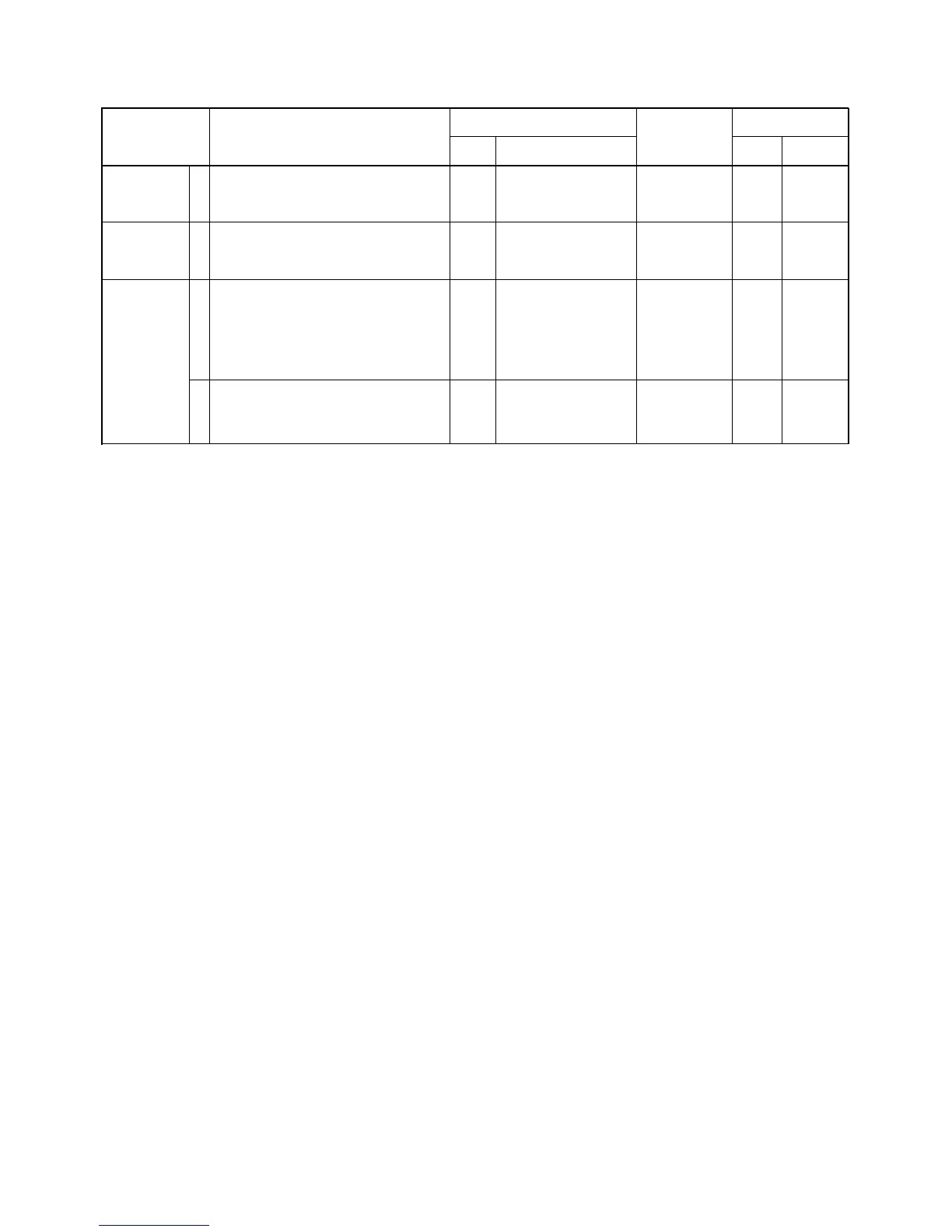
4-2 PLL ADJUSTMENT
TX VCO LOCK
VOLTAGE
RX VCO LOCK
VOLTAGE
REFERENCE
FREQUENCY
1
1
1
2
• LCD display : A01 LW TXREF 127
• Transmitting
• LCD display : A01 LW TXREF 127
• Receiving
• Wait for 5 minutes after power ON.
• LCD display : A01 LW TXREF
Connect an RF power meter or 50 Ω
dummy load to the [TX] antenna con-
nector.
• Transmitting
• LCD display : A01 LW RXREF
• Receiving
TX
RX
REAR
panel
RX
Connect a digital multi
meter or oscilloscope
to check point CP4.
Connect a digital multi
meter or oscilloscope
to check point CP3.
Loosely couple a fre-
quency counter to the
[TX] antenna connec-
tor.
Connect a frequency
counter to check point
CP2.
4.0 V
4.0 V
173.7250 MHz
142.2750 MHz
TVCO
RVCO
FRONT
FRONT
C17
C17
[PRT/BASE]
/[MONI]
[PRT/BASE]
/[MONI]
ADJUSTMENT ADJUSTMENT CONDITIONS
UNIT LOCATION
VALUE
UNIT ADJUST
MEASUREMENT ADJUSTMENT