4 - 7
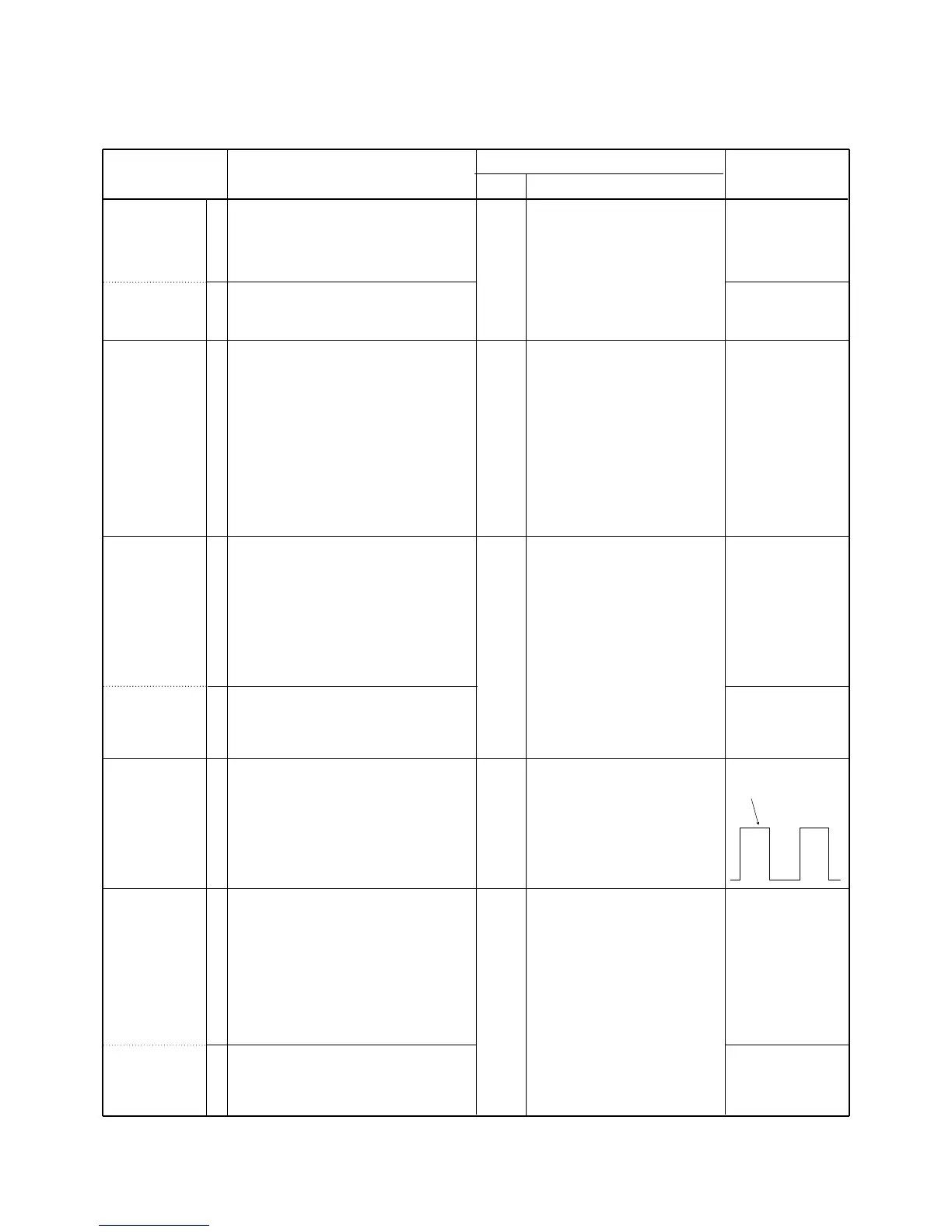
4-4 SOFTWARE ADJUSTMENT
Select an operation using [CH-UP] / [CH-DN] keys, then set specified value using [RPT/BASE] / [MONI] keys on the FRONT
PANEL.
1
2
1
2
1
2
• LCD display : A06 HW POWER
• Operating freq. : 465.2750 MHz
• Connect the RF power meter to the TX
antenna connector.
• Transmitting
• LCD display : A06 LW M POWER
• Operating freq. : 465.2750 MHz
• Transmitting
• LCD display : A07 LW M DEV
• Operating freq. : 465.2750 MHz
• IF bandwidth : Wide
• Connect an audio generator to the [MIC]
jack through the JIG cable and set as:
1.0 kHz/40 mVrms
• Set an FM deviation meter as:
HPF : OFF
LPF : 20 kHz
De-emphasis: OFF
Detector : (P–P)/2
• Transmitting
• LCD display : A10 LW CTCDEV
• Operating freq. : 465.2750 MHz
• Set the FM deviation meter as:
HPF : OFF
LPF : 20 kHz
De-emphasis: OFF
Detector : (P–P)/2
• No audio applied to the [MIC] connector.
• Transmitting
• LCD display : A12 LN CTCDEV
• Operating freq : 465.2750 MHz
• No audio applied to the [MIC] connector.
• Transmitting
• LCD display : A11 LW DTCADJ
• Operating freq. : 465.2750 MHz
• No audio applied to the [MIC] connector.
• Transmitting.
• LCD display : A13 LW RPTAF
• Operating freq : 460.2750 MHz (RX)
465.2750 MHz (TX)
• Connect a standard signal generator to
the RX antenna connector and set as:
Level : 1 mV* (–47 dBm)
Modulation : 1 kHz
Deviation : ±3 kHz
• Transmitting
• LCD display : A14 LN RPTAF
• Operating freq : 460.2750 MHz (RX)
465.2750 MHz (TX)
• Transmitting
OUTPUT
POWER
[Power (Hi)]
[Power (LOW)]
FM
DEVIATION
CTCSS
DEVIATION
[WIDE]
[NARROW]
MODULATION
BALANCE
[DTCS]
REPEATER
DEVIATION
[WIDE]
[NARROW]
Rear
panel
Rear
panel
Rear
panel
Rear
panel
Rear
panel
Connect an RF power meter to
the TX antenna connector.
Connect an FM deviation meter
to the TX antenna connector
through the attenuator.
Connect an FM deviation meter
to the TX antenna connector
through the attenuator.
Connect an FM deviation meter
with an oscilloscope to the TX
antenna connector through an
attenuator.
Connect an FM deviation meter
to the TX antenna connector
through the attenuator.
50.0 W
10.0 W
±4.5 kHz
±0.7 kHz
±0.35 kHz
±3.0 kHz
±1.5 kHz
ADJUSTMENT ADJUSTMENT CONDITION
MEASUREMENT
VALUE
UNIT LOCATION


 To Next Page