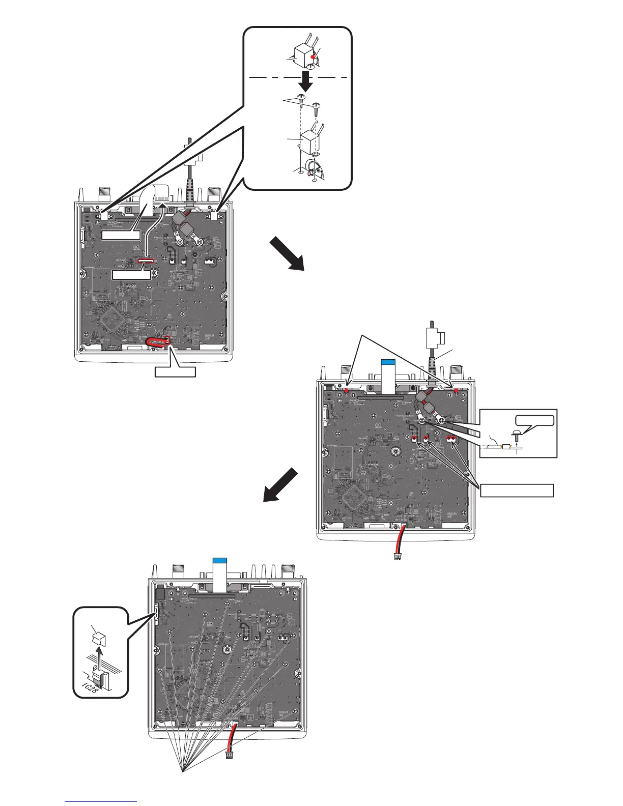
W4
W4
Unsolder 2 points
Unsolder 4 points
Unscrew
Clip
15 screws
w Unsolder 2 points at the ANT cases.
e Unscrew 4 screws from the ANT cases,
and remove them.
r Disconnect the flat cabe from J4 and the
speaker cable from J9.
t Unsolder 2 points at the bottom of ANT connectors.
y Unsolder 4 points at the PA module leads.
u Unscrew 2 screws from W4.
i Remove the clip from the side of chassis.
o Unscrew 15 screws from the MAIN UNIT, then take off
the MAIN UNIT PCB from the chassis.