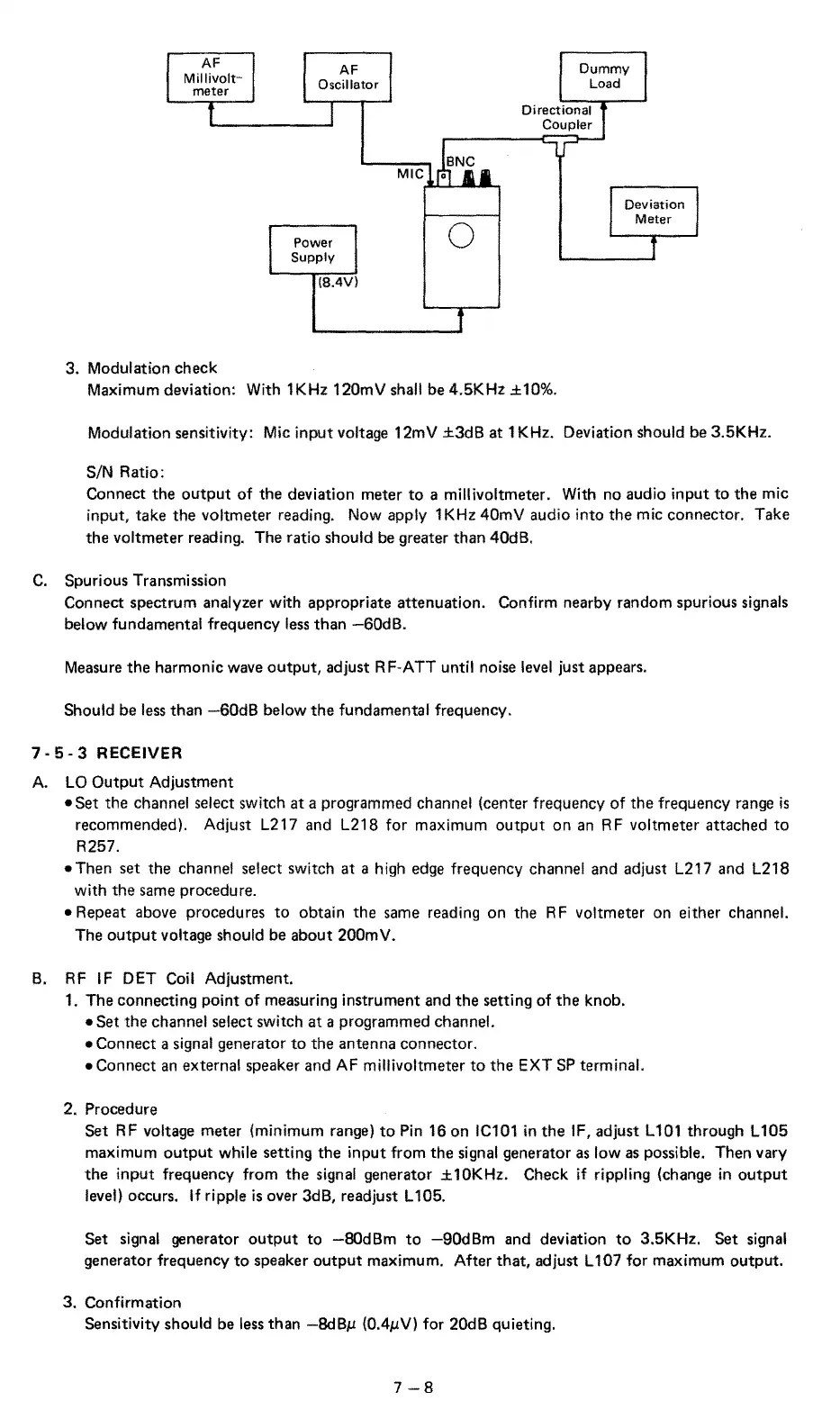
AF
Millivolt-
meter
AF
Oscillator
Dummy
Load
3. Modulation check
Power
Supply
{8.4V)
0
Directional
Coupler
Maximum deviation: With 1KHz 120mV shall be 4.5KHz ±10%.
Deviation
Meter
Modulation sensitivity:
Mic
input voltage 12mV
±3d8
at
1 KHz. Deviation should be 3.5KHz.
S/N Ratio:
Connect the
output
of
the deviation meter
to
a millivoltmeter. With no audio input
to
the
mic
input, take
the
voltmeter reading. Now apply
1KHz40mV
audio into
the
mic connector. Take
the
voltmeter reading. The ratio should be greater than 40dB.
C.
Spurious Transmission
Connect spectrum analyzer with appropriate attenuation. Confirm nearby random spurious
signals
below fundamental frequency less
than
-60dB.
Measure
the
harmonic wave
output,
adjust R F-ATT until noise level just appears.
Should be less than
-60d8
below
the
fundamental frequency.
7 ·
5-
3 RECEIVER
A.
LO
Output
Adjustment
•Set
the channel select switch
at
a programmed channel (center frequency
of
the
frequency range
is
recommended). Adjust L217 and L218 for maximum
output
on
an
RF voltmeter attached
to
R257.
•Then
set
the
channel select switch
at
a high edge frequency channel and adjust L217 and L218
with
the
same procedure.
•Repeat
above procedures
to
obtain the same reading on the
RF
voltmeter on either channel.
The
output
voltage should be about 200mV.
B.
RF
IF
DET Coil Adjustment.
1.
The connecting point
of
measuring instrument and
the
setting of
the
knob.
•Set
the channel select switch
at
a programmed channel.
•Connect
a signal generator
to
the antenna connector.
•Connect
an
external speaker and AF millivoltmeter
to
the
EXT
SP
terminal.
2. Procedure
Set
RF voltage meter (minimum range)
to
Pin 16 on IC101
in
the
IF, adjust
l101
through L105
maximum
output
while setting the input from
the
signal generator
as
low as possible. Then vary
the
input
frequency from
the
signal generator ± 10KHz. Check
if
rippling (change
in
output
level) occurs. If ripple
is
over
3d8,
readjust L 105.
Set signal
generator
output
to
-80dBm
to
-90dBm
and deviation
to
3.5KHz. Set signal
generator frequency
to
speaker
output
maximum. After
that,
adjust L 107 for maximum output.
3.
Confirmation
Sensitivity should be less than
-8dBµ
(0.4µV) for 20dB quieting.
7-8