EasyManua.ls Logo

Icom IC-M302 Service Manual

Icom IC-M302
41 pages
To Next Page IconTo Next Page
Page #1 background imageLoading...
Page #1 background image
SERVICE
MANUAL
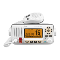
VHF MARINE TRANSCEIVER
M302

Other manuals for Icom IC-M302

Questions and Answers:

Icom IC-M302 Specifications

General IconGeneral
BrandIcom
ModelIC-M302
CategoryTransceiver
LanguageEnglish

Summary

Repair Notes

Section 1 Specifications

Section 3 Disassembly Instructions

Removing the Case

Step-by-step guide to removing the outer casing of the transceiver.

Removing the Main Unit

Instructions for safely disconnecting and removing the main internal unit.

Removing the Logic Board

Steps for safely removing the logic board from the transceiver assembly.

Section 4 Circuit Description

Section 5 Adjustment Procedures

5-1 Preparation

Lists required test equipment and connection diagrams for adjustments.

5-2 PLL Adjustments

Procedures for adjusting the Phase-Locked Loop for lock voltage and frequency.

5-3 Transmitter Adjustments

Procedures for adjusting transmitter output power and frequency deviation.

5-4 Receiver Adjustment

Procedure for adjusting receiver sensitivity.

Section 7 Mechanical Parts and Disassembly

Chassis Parts (Mechanical)

Lists mechanical chassis parts and their quantities for assembly.

Logic Board Parts (Mechanical)

Lists components and parts specific to the logic board assembly.

SQL Board Parts (Mechanical)

Lists components and parts specific to the SQL board assembly.

VR Unit Parts (Mechanical)

Lists components and parts specific to the VR (Variable Resistor) unit assembly.

Main Unit Parts (Mechanical)

Lists mechanical parts and fasteners for the main unit assembly.

Front Unit Parts (Mechanical)

Lists mechanical parts for the front unit, including microphones and speakers.

Chassis Parts Diagrams

Illustrates and labels chassis parts with reference numbers.

Logic Board Diagrams

Illustrates and labels logic board components with reference numbers.

Main Unit Diagrams (Page 23)

Illustrates and labels main unit components with reference numbers.

Section 10 Block Diagram

Section 11 Voltage Diagram

11-4 VR/SQL Board

11-5 HM-141

Related product manuals