4-2
• RX AF CIRCUITS
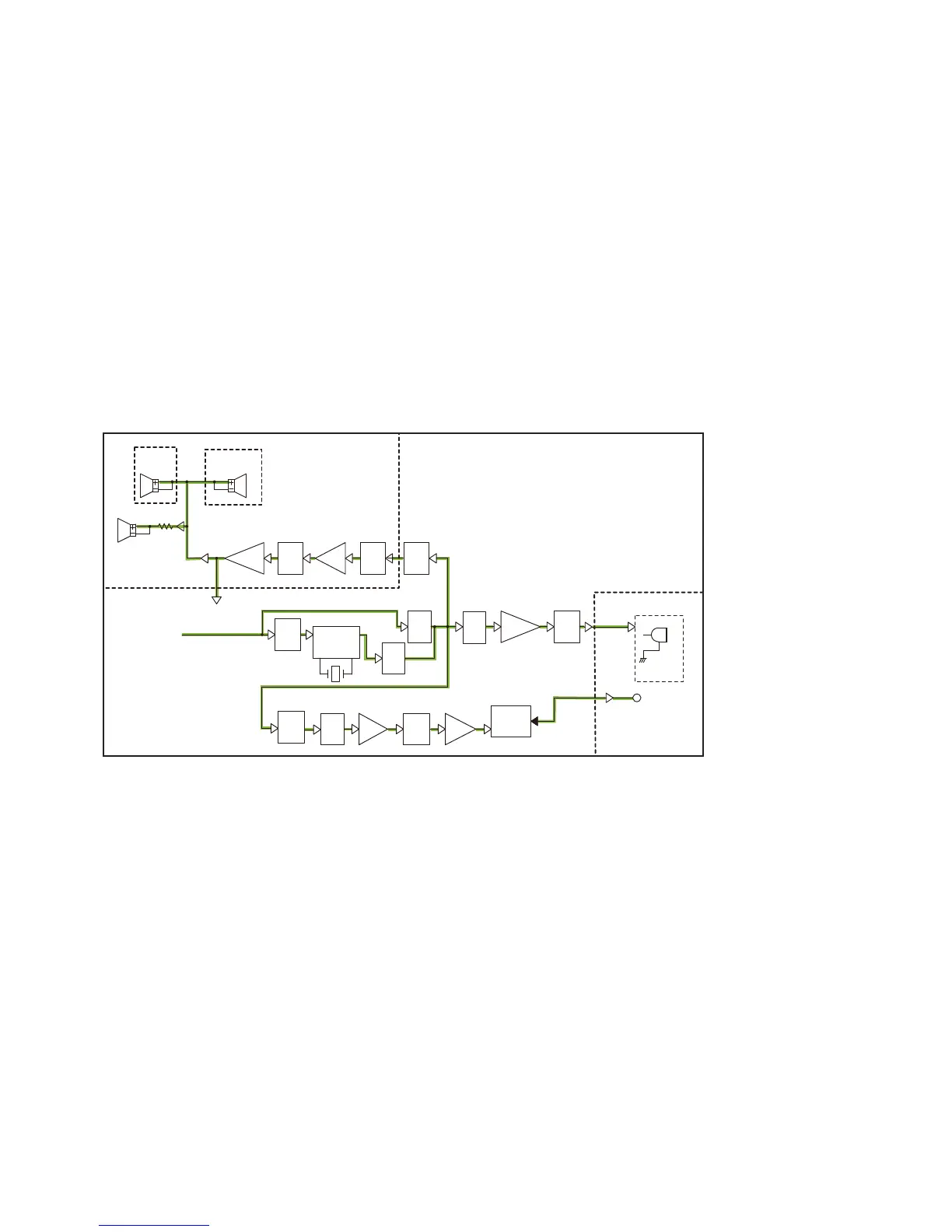
RX AF CIRCUITS (MAIN UNIT)
The demodulated AF signal from the AF SW (IC882) is passed
through the AF MUTE SW (IC505, pins 1, 2), de-emphasis
circuit (R551 and C236), BPF (IC506, pins 9, 8 and pins 6, 7)
and AF MUTE SW (IC906, pins 9, 8), and then applied to the
noise canceller IC (IC901, pin 31).
The processed AF signal is output from pin 37, and passed
through the AF SW (IC906, pins 1, 2).
•
When the AF signal is output to the front panel speaker,
external speaker, HM-205B or HM-205RB
The RX AF signal from the AF SW (IC906, pin 2) is passed
through the AF MUTE SW (IC504, pins 8, 9) and applied to
the D/A converter (IC702, pin 8) to be adjusted in level. The
level-adjusted signal is output from pin 7, and amplifi ed by
the AF AMP (IC707). The amplifi ed signal is AF power AMP
(IC701, pin 1), through the AF MUTE SW (IC703, pins 3, 1).
The amplifi ed signal is output to the internal speaker (CHAS-
SIS: SP1), external speaker, HM-205 or HM-205RB.
From the
demodulator circuits
AF
AMP
AF
MUTE
SP1
AF
MUTE
BUFF
AF
MUTE
AF
MUTE
AF
AMP
X901
SP1
AF
MUTE
AF
MUTE
SP1
1
R
AF
MUTE
AF
MUTEAF
MUTE
AF
AMP
AF
AMP
FRONT UNIT
MAIN UNIT
INT SP
IC503A:
IC503B:
HM-205B
OPTIONAL
IC502C:
IC506A:
COMMANDMIC
IC504C:
PA SP
(BTL AMP)
IC701B
IC701A
EXT SP(BTL AMP)
IC704
1A
EVOL
HM-205RB
AFMIC
IC702B
Relay
Q702
IC703
IC702A
(2CH)
Rec_Play
CANCELER
NOISE
RL1
D702
IC906A
IC906B
IC906C
EVOL
1B
IC707
IC706
IC901
HM-195
• When the AF signal is output to the optional HM-195
The RX AF signal from the AF SW (IC906, pin 2) is passed
through the AF MUTE SW (IC503, pins 2, 1) and amplifi ed by
the buffer (IC506, pins 4, 1), and then output to the HM-195,
through the AF mute SW (IC502, pins 9, 8).