4 - 7
4-7-3 CPU (LOGIC BOARD; IC1)
Input port for the low-battery detecting
signal. Low battery indicator appears
when the battery becomes less than
2.58 V
Input port for transmit detecting signal.
Input port for the indide temperature
detecting signal.
Input ports for the dial data signals.
Input port for the HM-136’s PTT button
detecting signal.
Low : While PTT button is pushed.
Input port for the microphone hanger
detecting signal
Low : The microphone on hook.
Outputs ATIS/DSC encode signals.
Outputs the voice scramber unit
(UT-112) control signal.
Outputs a strobe signal to the voice
scrambler unit (UT-112).
Outputs a strobe signal to the PLL IC
(MAIN unit; IC12, pin 3).
Outputs a strobe signal to the D/A
convertor IC (MAIN unit; IC15, pin 6).
I/O port for the communicating singal
from the microphone (HM-127/2) to
the transceiver.
I/O port for the communicating singal
from the transceiver to the micro-
phone (HM-127/2).
LBAT
TXDET
TEMP
DIAL1–
DIAL4
PTT
HANG
DSC
SCON
OPSTB
DASTB
PSTB
DATAH2M
DATAMH2
105
106
107
111–114
115
116
117
120
121
124
125
126
127
7
25
28
34
38
39
58
59
63
64
66
69
70
71
74
91
93
94
95
97
98
103
104
UNLK
EDATA
ECK
DEC3
.
DEC1
BEEP
DATAMC
DATACM
DATAMH1
DATAH1M
DATANM
DATAMN
PDATA
PCK
OPTIN
RMUTE
TMUTE
SEND
H/L
ATT1
ATT2
WXDEC
SQL
Input port for PLL unlock signal from
the PLL IC (MAIN unit; IC12, pin 7).
High : While PLL is unlocked.
I/O port for the data signals to the
EEPROM (IC4, pin 5).
Outputs a clock signal to the EEP-
ROM (IC4, pin 6).
Input port for the decode signal for
channel 70 receiver.
Input port for the ATIS/DSC decode
signals.
Outputs beep audio signals.
I/O port for the cloning data from the
transceiver.
I/O port for the cloning data to the
transceiver.
I/O port for the communicating signal
from the transceiver to the micro-
phone (HM-127/1).
I/O port for the communicating signal
from the microphone (HM-127/1) to
the transceiver.
I/O port for the GGA signals
I/O port for the NMEA data.
Outputs a data signal to the PLL IC
(MAIN unit; IC12, pin 5).
Outputs a clock signal to the PLL IC
(MAIN unit; IC12, pin 4).
Outputs the voice scrambler unit
(UT-112) detecting signal.
Low : While UT-112 is connecting.
Outputs RX muting signal.
High : While RX signal is muting.
Outputs transmit mute signal.
High : While TX muting.
Outputs T8 regulator control signal.
High: While transmitting.
Output port for RF output power (High
or Low) select signal.
Low : While Low power is selected.
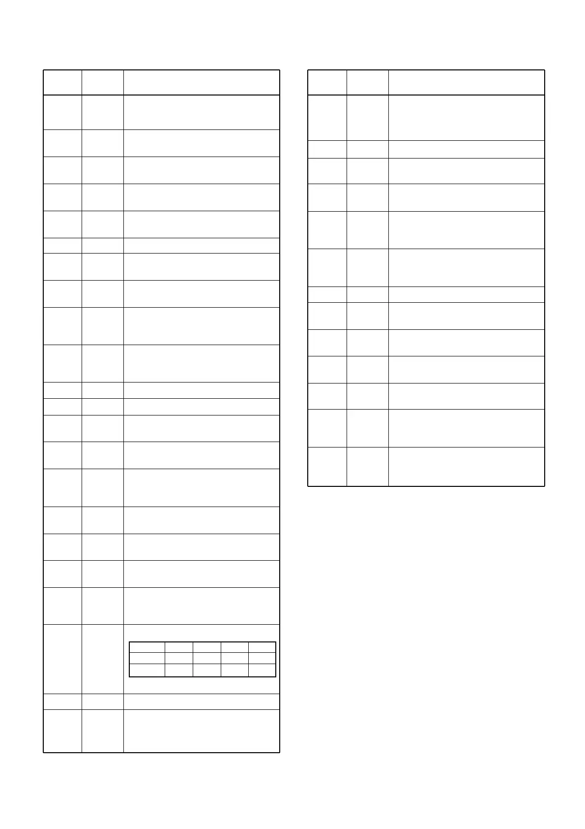
Output RX attenuator control signals.
Input port for the weather alert signal.
Input port for the FM IF IC (MAIN unit;
IC1, pin 14)’s noise amplifier detecting
signal.
Pin Port
Description
number name
Pin Port
Description
number name
ATT level
ATT1
ATT2
OFF
1
1
ON (1)
1
0
ON (2)
0
1
MAX.
1
1