EasyManua.ls Logo

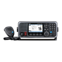
Icom IC-M602 Service Manual

Icom IC-M602
53 pages
To Next Page IconTo Next Page
Page #1 background imageLoading...
Page #1 background image
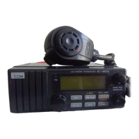
VHF MARINE TRANSCEIVER
iM602
SERVICE
MANUAL

Other manuals for Icom IC-M602

Questions and Answers:

Icom IC-M602 Specifications

General IconGeneral
TypeMarine VHF Transceiver
Frequency Range156.000 - 163.425 MHz
Antenna Impedance50Ω
Weight1.5 kg
Waterproof RatingIPX7
Modulation SystemFM
Sensitivity0.25 μV (12 dB SINAD)
Intermodulation Rejection Ratio70 dB
Spurious Response Rejection Ratio70 dB
Audio Output Impedance
Output Power25W / 1W
Power Supply13.8 V DC
Operating Temperature Range-15°C to +55°C
Adjacent Channel Power70 dB
FM Hum and Noise40 dB
Squelch Sensitivity0.25 μV
Usable ChannelsUSA, Canada, International
Type of Emission16K0G3E (FM), 16K0G2B (DSC)
Current Drain5.5 A (at 25 W), 1.5 A (at 1 W)
Spurious Emissions-70 dBc (High), -60 dBc (Low)

Summary

Introduction, Safety, and Repair

Introduction

Describes service information for the IC-M602 transceiver.

Danger Warnings

Critical safety warnings to prevent equipment damage or personal injury.

Repair and Parts Ordering

Essential guidelines for safe repair and ordering replacement parts.

Specifications

General Specifications

Overall technical specifications including frequency, modes, and power.

Transmitter & Receiver Specs

Performance specifications for transmitter and receiver sections.

Inside Views

IC-M602 Unit Views

Top views of the main unit and logic board with component labels.

HM-127 Microphone Views

Top and bottom views of the HM-127 microphone with component labels.

Disassembly Instructions

Opening Transceiver Case

Steps to open the transceiver case by removing screws.

Removing Major Units

Procedures for removing the main, logic, and AF units.

Circuit Descriptions

Receiver Circuits

Explanation of receiver circuit functions and stages.

Transmitter Circuits

Explanation of transmitter circuit functions and stages.

PLL, Logic, DSC, Power Circuits

Descriptions of PLL, logic, DSC, and power supply circuits.

Adjustment Procedures

Preparation and Equipment

Required test equipment and connection setup for adjustments.

PLL and Receiver Adjustments

Procedures for adjusting PLL lock voltage and receiver sensitivity.

Parts Lists

IC-M602 Component Parts

Parts list for the IC-M602 unit, including boards.

Accessory Component Parts

Parts lists for the HM-136 and HM-127 microphone accessories.

Mechanical Parts

IC-M602 Mechanical Parts

Lists chassis, unit, and board mechanical parts for IC-M602.

Accessory Mechanical Parts

Lists mechanical parts for the HM-136 and HM-127 microphones.

Semiconductor Information

Transistors and FETs

Diagrams and identification of transistors and FETs used.

Diodes

Diagrams and identification of diodes used.

Board Layouts: VR, SQL, Dial, Connect

VR, SQL, Dial Board Layouts

Visual layouts for VR, SQL, and Dial boards.

Connect Unit Board Layouts

Top and bottom views of the Connect Unit board.

Board Layouts: Logic and Main Units

Logic Board Layouts

Top and bottom views of the Logic unit board.

Main Unit Board Layouts

Top and bottom views of the Main unit board.

Board Layouts: AF Unit and Accessories

AF Unit Board Layouts

Top and bottom views of the AF unit board.

Accessory Board Layouts

Top and bottom views for HM-136 and HM-127 circuit boards.

System Diagrams

Block Diagram

Overall functional block diagram of the transceiver system.

Wiring and Voltage Diagrams

Diagrams showing wiring, voltage, and connections between units.