EasyManua.ls Logo

Icom IC-M601 Service Manual

Icom IC-M601
54 pages
To Next Page IconTo Next Page
Page #1 background imageLoading...
Page #1 background image
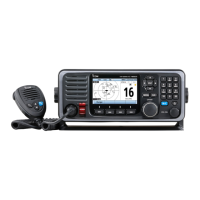
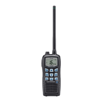
VHF MARINE TRANSCEIVER
iM601
SERVICE
MANUAL

Other manuals for Icom IC-M601

Questions and Answers:

Icom IC-M601 Specifications

General IconGeneral
TypeMarine VHF Transceiver
Waterproof RatingIPX7
Output Power25W
ModulationFM
Current Consumption5.5 A (at 25 W TX)
Power Supply13.8V DC ±15%

Summary

INTRODUCTION

DANGER

Critical safety warnings to prevent damage to the transceiver and personal injury.

ORDERING PARTS

Procedure for ordering replacement parts, specifying required information.

REPAIR NOTES

Important guidelines and precautions for servicing and repairing the transceiver.

SECTION 1 SPECIFICATIONS

GENERAL SPECIFICATIONS

General operating and physical specifications of the VHF marine transceiver.

TRANSMITTER SPECIFICATIONS

Technical specifications detailing transmitter output power, modulation, and performance.

RECEIVER SPECIFICATIONS

Technical specifications detailing receiver sensitivity, selectivity, and audio output.

VHF MARINE CHANNEL LIST

SECTION 2 INSIDE VIEWS

2-1 IC-M601 MAIN UNIT AND LOGIC BOARD VIEWS

Component layouts for the IC-M601 main unit and logic board.

2-2 HM-134 (OPTIONAL UNIT) VIEWS

HM-134 TOP AND BOTTOM VIEWS

Component layouts for the HM-134 optional unit, showing top and bottom views.

SECTION 3 DISASSEMBLY AND OPTIONS INSTRUCTIONS

TRANSCEIVER CASE AND MAIN UNIT DISASSEMBLY

Procedures for opening the transceiver case and removing the main unit.

LOGIC BOARD DISASSEMBLY

Steps for safely removing the logic board from the transceiver.

AF UNIT DISASSEMBLY

UT-112 VOICE SCRAMBLER INSTALLATION

SECTION 4 CIRCUIT DESCRIPTION

4-1 RECEIVER CIRCUITS

Description of the transceiver's receiver circuitry, including RF and mixer stages.

4-1-3 1ST MIXER AND 1ST IF CIRCUITS

Description of the first mixer and intermediate frequency (IF) stages.

4-1-4 2ND IF AND DEMODULATOR CIRCUITS

CHANNEL 70 AND OTHER CHANNELS CIRCUITS

Description of receiver circuits for channel 70 and other channels.

4-1-5 AF AMPLIFIER CIRCUIT

4-1-6 SQUELCH CIRCUIT

4-2 TRANSMITTER CIRCUITS

4-2-1 MICROPHONE AMPLIFIER CIRCUIT

Description of the microphone amplifier circuit for audio input.

4-2-2 MODULATION CIRCUIT

4-2-3 PRE-DRIVE AND YGR AMPLIFIERS

4-2-4 POWER AMPLIFIER CIRCUIT

4-2-5 APC CIRCUIT

4-3 PLL CIRCUITS

PLL CIRCUIT GENERAL AND LOOPS

General description and operation of Phase-Locked Loop (PLL) circuits.

4-3-3 OTHER CHANNELS (RX) LOOP

4-3-4 VCO CIRCUIT

4-4 DSC CIRCUITS

DSC MODULATION CIRCUIT

Description of the DSC modulation circuit for signal encoding.

4-5 LOGIC CIRCUITS

MAIN UNIT LOGIC CIRCUITS

Description of the main unit's logic circuits, including CPU and clock.

4-6 POWER SUPPLY CIRCUITS

VOLTAGE LINES IN MAIN UNIT

Description of voltage lines and their distribution in the main unit.

4-7 PORT ALLOCATIONS

EXPANDER IC PORT ALLOCATIONS

Port allocations for expander ICs on the AF unit.

4-7-3 CPU (LOGIC BOARD; IC1) PIN DESCRIPTIONS

SECTION 5 ADJUSTMENT PROCEDURES

5-1 PREPARATION FOR ADJUSTMENTS

Preparation steps, including required test equipment and connections.

5-2 PLL ADJUSTMENTS

PLL ADJUSTMENT POINTS AND VIEWS

Visual guide and locations for PLL lock voltage adjustments.

5-3 RECEIVER ADJUSTMENTS

RECEIVER SENSITIVITY ADJUSTMENTS

Procedures for adjusting receiver sensitivity on various channels.

MAIN UNIT TOP VIEW FOR RECEIVER ADJUSTMENT

SECTION 6 PARTS LIST

6-1 IC-M601 PARTS LIST

List of parts for the IC-M601 transceiver.

LOGIC BOARD PARTS LIST

AF UNIT PARTS LIST

LOGIC BOARD PARTS LIST (CONTINUED)

AF UNIT PARTS LIST (CONTINUED)

AF UNIT PARTS LIST (CONTINUED)

AF UNIT PARTS LIST (CONTINUED)

MAIN UNIT PARTS LIST

MAIN UNIT PARTS LIST (CONTINUED)

MAIN UNIT PARTS LIST (CONTINUED)

MAIN UNIT PARTS LIST (CONTINUED)

MAIN UNIT PARTS LIST (CONTINUED)

6-3 HM-134 (OPTIONAL MICROPHONE) PARTS LIST

HM-134 CHASSIS AND RELATED MAIN UNIT PARTS

Parts list for the HM-134 chassis and related main unit components.

MAIN UNIT PARTS LIST (CONTINUED)

SECTION 7 MECHANICAL PARTS AND DISASSEMBLY

7-1 IC-M601 MECHANICAL PARTS AND DISASSEMBLY

Mechanical parts and disassembly instructions for the IC-M601.

7-2 HM-137 MECHANICAL PARTS

HM-137 CHASSIS AND RELATED MAIN UNIT PARTS

Chassis and main unit parts for the HM-137 microphone.

7-3 HM-134 MECHANICAL PARTS

HM-134 CHASSIS, MAIN UNIT, AND ACCESSORIES PARTS

Chassis, main unit, and accessories parts for the HM-134 microphone.

SECTION 8 SEMI-CONDUCTOR INFORMATION

TRANSSISTORS, FET'S, AND DIODES INFORMATION

Information and symbols for transistors, FETs, and diodes used in the unit.

SECTION 9 BOARD LAYOUTS

VR, SQL, AND DIAL BOARD LAYOUTS

Layouts of the VR, SQL, and Dial boards.

CONNECT-A UNIT BOARD LAYOUT

Layout of the Connect-A unit, including top and bottom views.

9-5 LOGIC BOARD TOP VIEW

LOGIC BOARD BOTTOM VIEW

9-6 MAIN UNIT TOP VIEW

MAIN UNIT BOTTOM VIEW

9-7 AF UNIT TOP VIEW

AF UNIT BOTTOM VIEW

9-8 HM-137 TOP VIEW

9-9 HM-134 (OPTIONAL UNIT) TOP VIEW

HM-134 AND HM-137 BOTTOM VIEWS

SECTION 10 BLOCK DIAGRAM

SECTION 11 WIRING DIAGRAM

SECTION 12 VOLTAGE DIAGRAMS

12-1 LOGIC BOARD VOLTAGE DIAGRAM

Voltage diagram illustrating power distribution on the logic board.

12-2 MAIN UNIT VOLTAGE DIAGRAM

12-3 AF UNIT VOLTAGE DIAGRAM

12-4 HM-137 VOLTAGE DIAGRAM

12-5 HM-134 (OPTIONAL UNIT) VOLTAGE DIAGRAM

Related product manuals