4 - 7
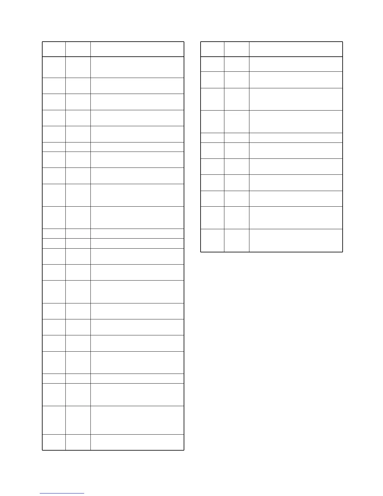
4-7-3 CPU (LOGIC BOARD; IC1)
Input port for the indide temperature
detecting signal.
Input ports for the dial data signals.
Input port for the HM-137’s PTT button
detecting signal.
Low : While PTT button is pushed.
Input port for the microphone hanger
detecting signal.
Low : The microphone on hook.
Outputs ATIS/DSC encode signals.
Outputs the voice scramber unit
(UT-112) control signal.
Outputs a strobe signal to the voice
scrambler unit (UT-112).
Outputs a strobe signal to the PLL IC
(MAIN unit; IC12, pin 3).
Outputs a strobe signal to the D/A
convertor IC (MAIN unit; IC15, pin 6).
I/O port for the communicating singal
from the microphone (HM-134/2) to
the transceiver.
I/O port for the communicating singal
from the transceiver to the micro-
phone (HM-134/2).
TEMP
DIAL1–
DIAL4
PTT
HANG
DSC
SCON
OPSTB
DASTB
PSTB
DATAH2M
DATAMH2
107
111–114
115
116
117
120
121
124
125
126
127
7
25
28
34
38
39
58
59
63
64
66
69
70
71
74
91
93
94
95
103
104
105
106
UNLK
EDATA
ECK
DEC3
.
DEC1
BEEP
DATAMC
DATACM
DATAMH1
DATAH1M
DATANM
DATAMN
PDATA
PCK
OPTIN
RMUTE
TMUTE
SEND
H/L
WXDEC
SQL
LBAT
TXDET
Input port for PLL unlock signal from
the PLL IC (MAIN unit; IC12, pin 7).
High : While PLL is unlocked.
I/O port for the data signals to the
EEPROM (IC4, pin 5).
Outputs a clock signal to the EEP-
ROM (IC4, pin 6).
Input port for the decode signal for
channel 70 receiver.
Input port for the ATIS/DSC decode
signals.
Outputs beep audio signals.
I/O port for the cloning data from the
transceiver.
I/O port for the cloning data to the
transceiver.
I/O port for the communicating signal
from the transceiver to the micro-
phone (HM-134/1).
I/O port for the communicating signal
from the microphone (HM-134/1) to
the transceiver.
I/O port for the GGA signals
I/O port for the NMEA data.
Outputs a data signal to the PLL IC
(MAIN unit; IC12, pin 5).
Outputs a clock signal to the PLL IC
(MAIN unit; IC12, pin 4).
Outputs the voice scrambler unit
(UT-112) detecting signal.
Low : While UT-112 is connecting.
Outputs RX muting signal.
High : While RX signal is muting.
Outputs transmit mute signal.
High : While TX muting.
Outputs T8 regulator control signal.
High: While transmitting.
Output port for RF output power (High
or Low) select signal.
Low : While Low power is selected.
Input port for the weather alert signal.
Input port for the FM IF IC (MAIN unit;
IC1, pin 14)’s noise amplifier detecting
signal.
Input port for the low-battery detecting
signal. Low battery indicator appears
when the battery becomes less than
2.58 V.
Input port for transmit detecting signal.
Pin Port
Description
number name
Pin Port
Description
number name