EasyManua.ls Logo

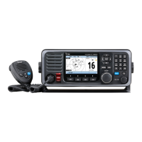
Icom IC-M604 Service Manual

Icom IC-M604
50 pages
To Next Page IconTo Next Page
Page #1 background imageLoading...
Page #1 background image
S-14306MZ-C1
Aug. 2006
SERVICE
MANUAL
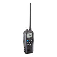
VHF MARINE TRANSCEVER
iC-m604

Other manuals for Icom IC-M604

Questions and Answers:

Icom IC-M604 Specifications

General IconGeneral
BrandIcom
ModelIC-M604
CategoryTransceiver
LanguageEnglish

Summary

Introduction and Safety

Danger Warnings

Critical safety warnings for connecting power and handling the transceiver.

Specifications

General Specifications

Covers frequency coverage, mode, power supply, temperature, dimensions, and weight.

Transmitter Specifications

Details output power, modulation, frequency deviation, stability, and emissions.

Receiver Specifications

Details receive system, IF, sensitivity, selectivity, and audio output.

VHF Marine Channel List

Inside Views

IC-M604 Main and Logic Units

Identifies major components and boards within the main and logic units.

HM-157 Optional Product Views

Shows top and bottom views of the HM-157 microphone's internal components.

Disassembly Instructions

Opening the Transceiver Case

Step-by-step guide for safely opening the transceiver casing.

Removing Major Units

Instructions for detaching the Logic Unit, Main Unit, and AF Unit.

Circuit Description

Receiver Circuits

Explains antenna switching, RF amplification, and mixer/IF stages.

Transmitter Circuits

Details microphone amplifier, modulation, pre-drive, and power amplifier circuits.

PLL Circuits

Describes Phase-Locked Loop operation for frequency synthesis.

DSC Circuits

Covers ATIS/DSC modulation and related signal processing.

Logic Circuits

Explains the CPU, system clock, and reset functions.

Power Supply Circuits

Details voltage lines and regulators within the main unit.

Port Allocations

Describes pin assignments for expander ICs on AF and other units.

Adjustment Procedures

Preparation and Test Equipment

Lists required test equipment and connection setup for adjustments.

PLL Adjustments

Procedure for adjusting PLL lock voltage for TX and RX.

Receiver Sensitivity Adjustments

Steps for setting receiver sensitivity for different channels.

Parts List

IC-M604 Replacement Units and Front Unit Parts

Lists replacement parts for the IC-M604 and its front unit.

Logic Unit Parts

Lists components for the logic board.

AF Unit Parts

Lists components for the audio frequency unit.

Main Unit Parts

Lists components for the main circuit board.

Accessories Parts

Lists parts for optional accessories.

Mechanical Parts

IC-M604 Chassis and Front Unit Parts

Lists chassis and front unit mechanical components for the IC-M604.

IC-M604 Logic, AF, and Connect Unit Parts

Lists mechanical parts for logic, AF, and connect units.

HM-126RB/RG and HM-157 Mechanical Parts

Lists mechanical components for the HM-126RB/RG and HM-157 accessories.

Semiconductor Information

Transistors and FETs

Displays symbols and common types for transistors and FETs used.

Diodes

Displays symbols and common types for diodes used in the device.

Board Layouts

VR, SQL, Dial, and Connect Unit Layouts

Top and bottom views showing component placement on VR, SQL, Dial, and Connect units.

Logic Unit Layouts

Top and bottom views illustrating component placement on the logic board.

Main Unit Layouts

Top and bottom views showing component placement on the main unit's PCB.

AF Unit Layouts

Top and bottom views illustrating component placement on the AF unit's PCB.

Microphone Layouts

Top and bottom views of HM-126RB/RG and HM-157 microphone PCBs.

Block Diagram

Wiring Diagram

Voltage Diagrams

Logic Unit Voltage Diagram

Shows voltage distribution and levels on the logic unit.

Main Unit Voltage Diagram

Illustrates voltage distribution and levels on the main unit.

AF Unit Voltage Diagram

Shows voltage distribution and levels on the AF unit.

Microphone Voltage Diagrams

Displays voltage diagrams for HM-126RB/RG and HM-157 microphones.