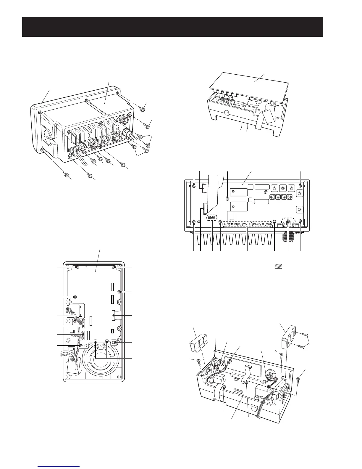
4. Removing the AF UNIT
1 Disconnect 4 connectors from J5, J8, J9 and J10.
2 Disconnect 2 flat cables from J2 and J4
3 Unscrew 2 screws H, and remove 2 clips I, J.
4 Unscrew 3 screws K, and remove the AF UNIT.
1. Opening the transceiver case
1 Unscrew 6 screws A, and remove the front unit.
2 Unscrew 6 screws B, and remove the rear panel.
2. Removing the LOGIC UNIT
1 Disconnect connector from J5 and flat cables from J1,
J2 and J6.
2 Unsolder 2 points C.
3 Disconnect microphone connector from J4 and SQL/
DIAL connectors from J7.
4 Unscrew 7 screws D, and remove the LOGIC UNIT.
3. Removing the MAIN UNIT
1 Remove the shield cover E.
2 Disconnect flat cables from J1 and J2.
3 Unsolder 17 points F.
4 Unscrew 7 screws G, and remove the MAIN UNIT.
SECTION 3 DISASSEMBLY AND OPTIONS INSTRUCTIONS
3 - 1