SECTION 3 DISASSEMBLY AND OPTIONS INSTRUCTIONS
• Opening the transceiver case
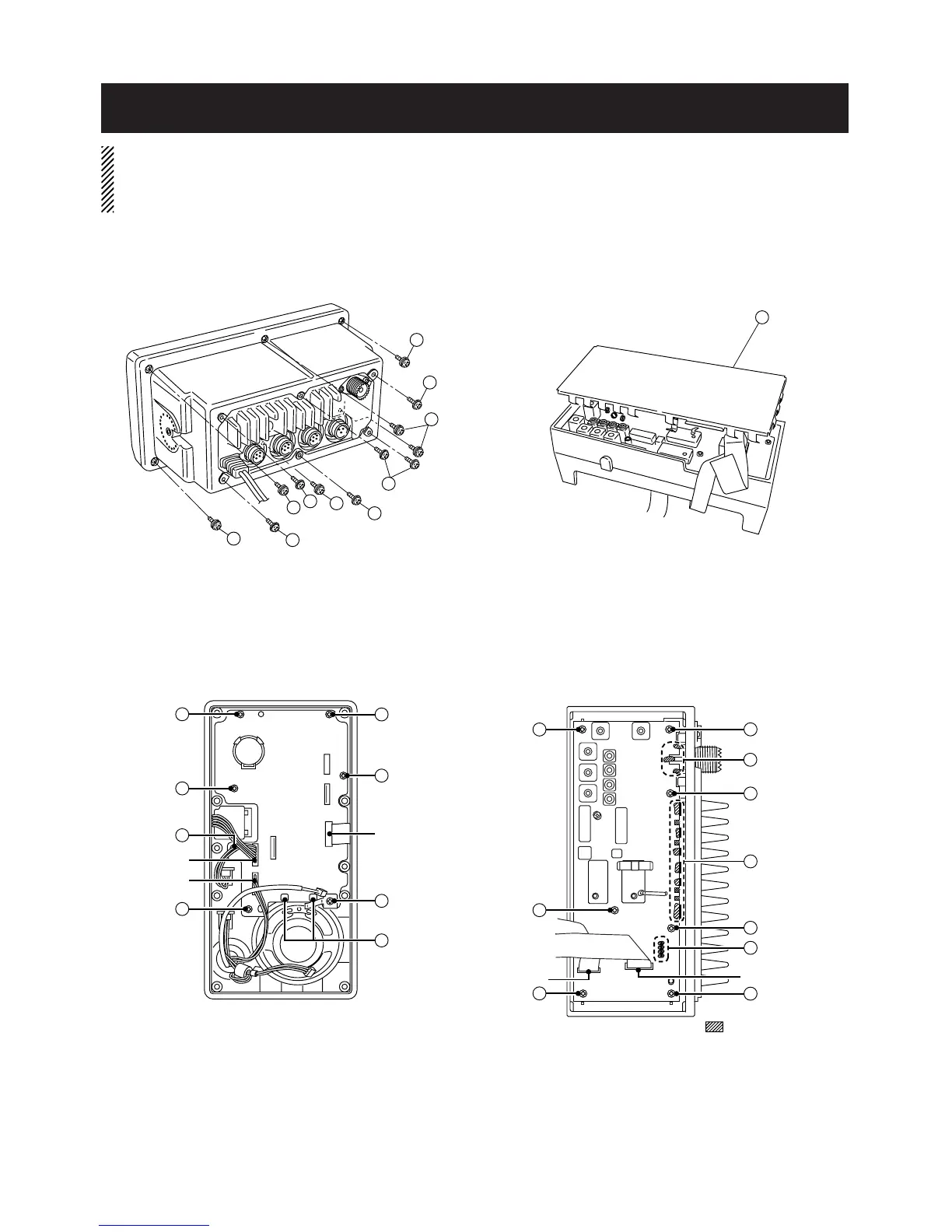
1 Unscrew 6 screws A, and remove the front unit.
2 Unscrew 6 screws B, and remove the rear panel.
CAUTION: DISCONNECT the DC power cable from the
transceiver before performing any work on the transceiver.
Otherwise, there is danger of electric shock and/or equip-
ment damage.
• Removing the LOGIC board
1 Unsolder 2 points C.
2 Disconnect microphone connector from J4 and
SQL/DIAL connector from J7.
3 Unscrew 7 screws D, and remove the LOGIC board.
• Removing the MAIN unit
1 Remove the shield cover E.
2 Disconnect flat cables from J1 and J2.
3 Unsolder 17 points F.
4 Unscrew 7 screws G, and remove the MAIN unit.
3 - 1