61
13
CONFECTION AND INSTALLATION
13
2001 NEW
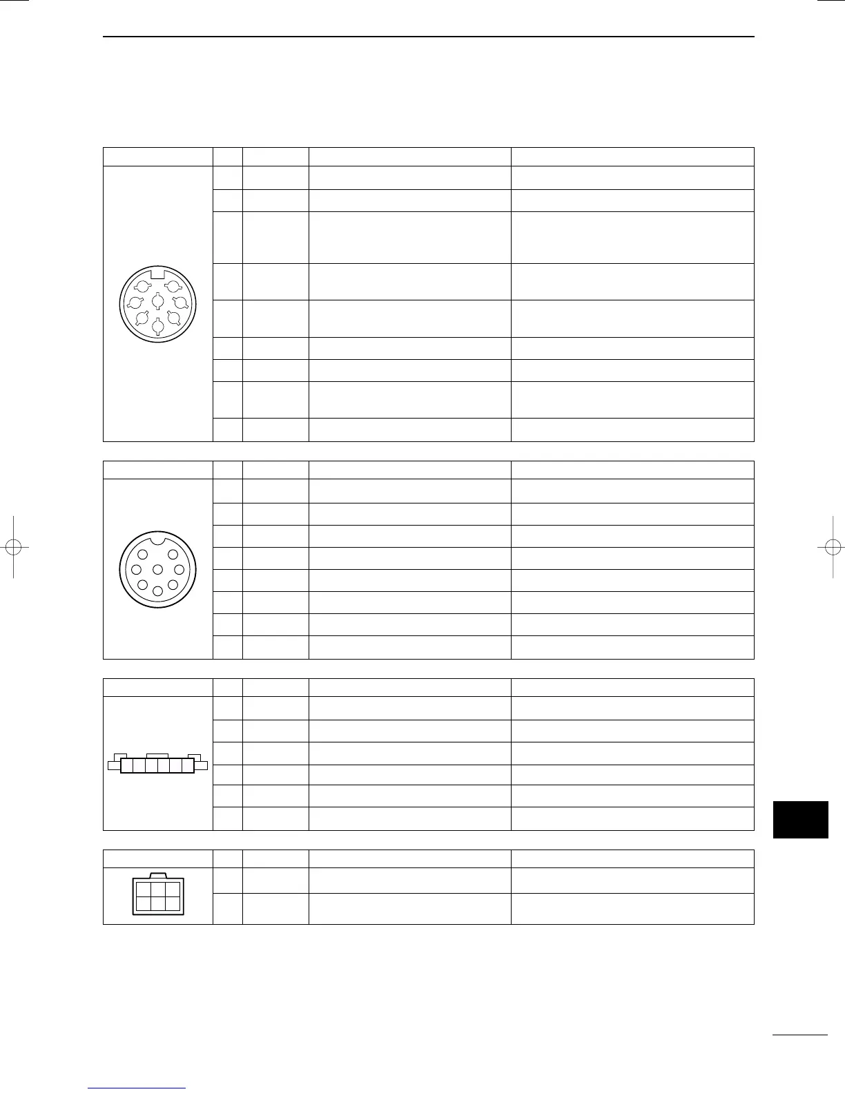
■ Connector information
ACC Pin Pin name Description Specification
1 CWK CW and FSK keying input. Input level :
Less than 0.6 V for transmit
2 AF GND Ground line for AF signal.
Input/output pin. Ground level : –0.5 to 0.8 V
3 SEND Goes to ground when transmitting. Input current : Less than 20 mA
When grounded, transmits.
4 MOD Modulator input. Input impedance : 5 kΩ
Usable when pin 3 is grounded. Input level : Approx. 100 mV rms
5 AF AF detector output. Output impedance: 4.7 kΩ
Fixed, regardless of [VOL] position. Output level : 100–300 mV rms
6 NC No connection
7 13.6 V 13.6 V output when power is ON. Output current : max. 1 A
8 ALC ALC voltage input. Control voltage : –3 to 0 V
Input impedance : More than 10 kΩ
* DC GND Common ground.
1
2
3
4
5
6
7
8
MICROPHONE Pin Pin name Description Specification
1 MIC+ Audio input from the mic element. Input impedance : 2.4 kΩ
2 NC No connection
3 AF1 AF output controlled with [VOL].
4 AF2 Ground for AF1.
5 PTT PTT switch input. When grounded, transmits.
6 GND Connected to the ground.
7 MIC– Coaxial ground for MIC+.
8AF– Coaxial ground for AF1 and AF2.
y
t
r
q
w
e
i
u
DC 13.6V Pin Pin name Description Specification
1–3 + DC input +. Max. power consumption 30 A typical.
4–6 _ DC input _.
1 2
4 6
3
5
TUNER Pin Pin name Description Specification
1 KEY Key signal input. –0.5 to 0.8 V during tuning
2 START Start/through signal output
3 13.6V 13.6 V output
4 E Negative terminal
5 NC No connection
6 NC No connection
65432
1
*
IC-M802_USA.qxd 02.5.30 11:40 Page 61

 Loading...