3-2
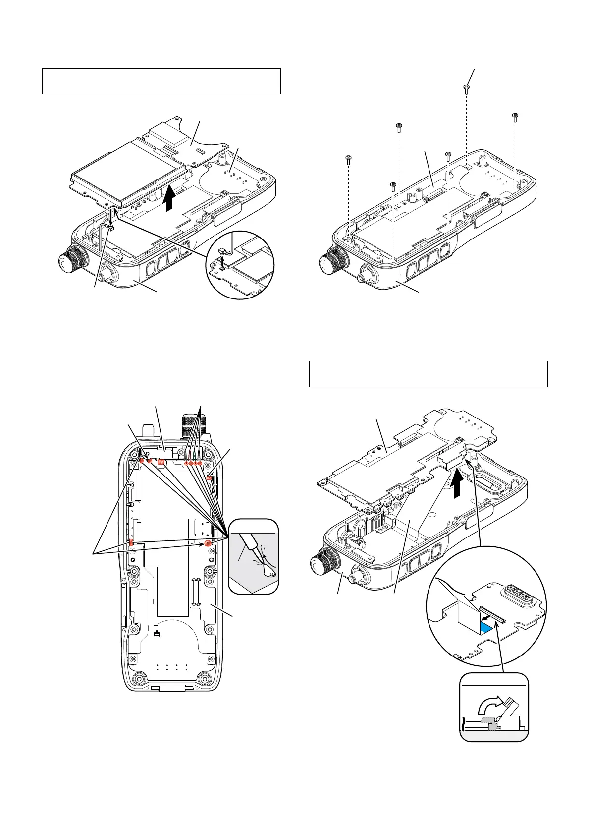
3) Separate the LOGIC/-1 UNIT from the MAIN UNIT, and
then disconnect the coaxial cable from the LOGIC/-1
UNIT.
BE CAREFUL about the coaxial cable when separating
the LOGIC/-1 UNIT from the MAIN UNIT.
Screws ×6
Rear panel
Rear panel
LOGIC/-1 UNIT
Rear panel
Coaxial cable
MAIN UNIT
Antenna plate
Bar antenna wires
Earth plates
UNSOLDER
Solder
remover
Jumper wire
Antenna connector
MAIN UNIT
MAIN UNIT
FLAT CABLE
Lift up
flat cable
Screws ×6
Rear panel
Rear panel
LOGIC/-1 UNIT
Rear panel
Coaxial cable
MAIN UNIT
Antenna plate
Bar antenna wires
Earth plates
UNSOLDER
Solder
remover
Jumper wire
Antenna connector
FLAT CABLE
Lift up
flat cable
3. REMOVING THE MAIN UNIT
1) Unsolder 3 points at the earth plate, a point at jumper
wire, a point at antenna connector, a point at antenna
plate and 4 points at the bar antenna wires.
3) Separate the MAIN UNIT from the rear panel, and then
disconnect the flat cable from the MAIN UNIT.
BE CAREFUL about the flat cable when separating the
MAIN UNIT from the rear panel.
Screws ×6
Rear panel
LOGIC/-1 UNIT
Rear panel
Coaxial cable
MAIN UNIT
MAIN UNIT
Antenna plate
Bar antenna wires
Earth plates
UNSOLDER
Solder
remover
Jumper wire
Antenna connector
MAIN UNIT
MAIN UNIT
FLAT CABLE
Lift up
flat cable
Rear panel
Rear panel
LOGIC/-1 UNIT
Rear panel
Coaxial cable
MAIN UNIT
MAIN UNIT
Antenna plate
Bar antenna wires
Earth plates
UNSOLDER
Solder
remover
Jumper wire
Antenna connector
MAIN UNIT
FLAT CABLE
Lift up
flat cable
Flat cable
2) Remove the 6 screws from the MAIN UNIT.

 Loading...