2 - 3
2-3 PLL CIRCUITS
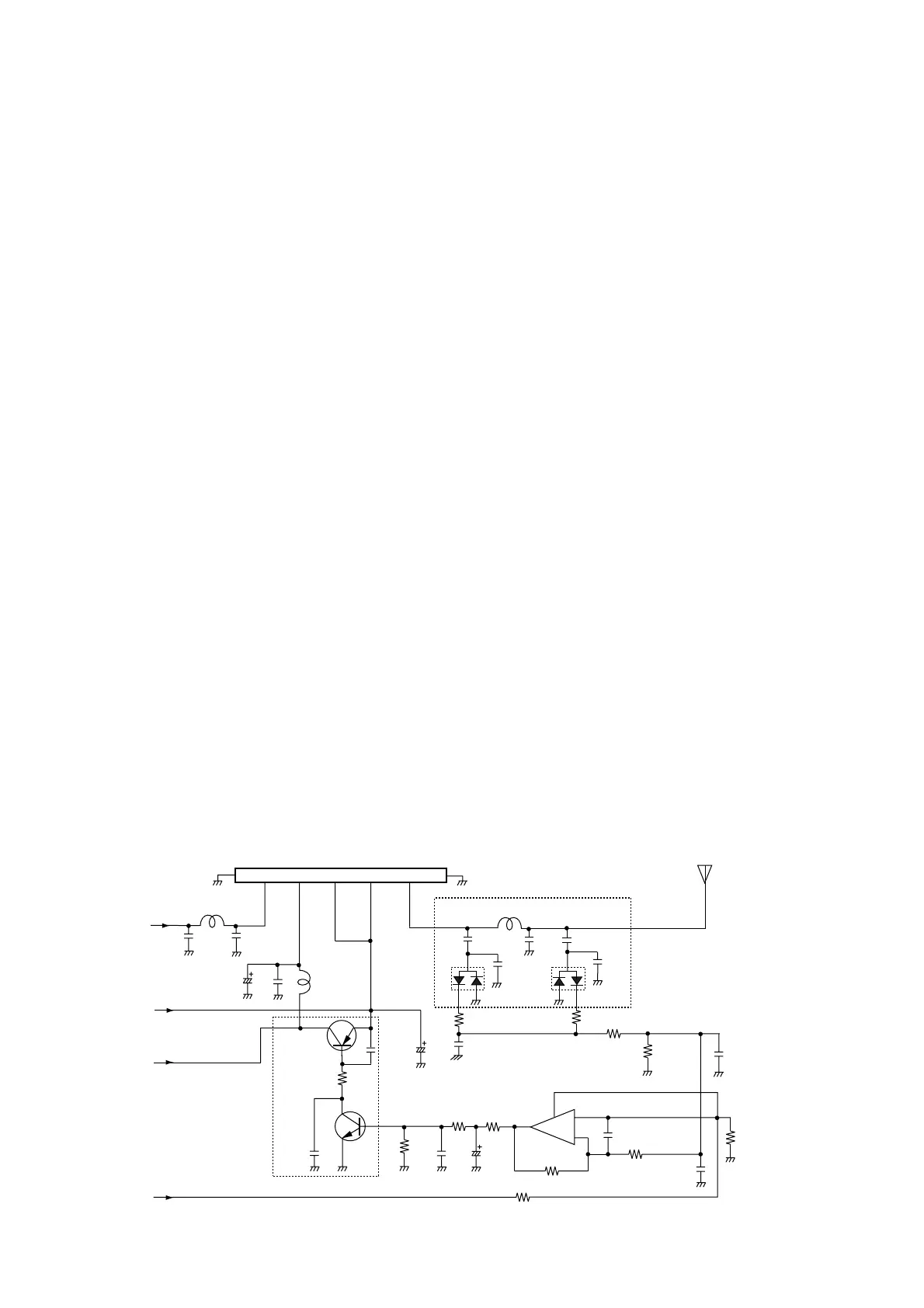
2-3-1 GENERAL
Each receiver and transmitter circuit has an independent
PLL circuit for controlling frequencies. All PLL circuits are
shielded and installed on the RX and TX Units.
PLL circuits steadily oscillate the transmit frequency and the
receive local frequency. The PLL output frequency is con-
trolled by the divided ratio (N-data) of the program mable
divider.
2-3-2 RECEIVER PLL CIRCUIT (RX UNIT)
The PLL IC (IC3) which includes in the prescaler, the pro-
grammable counter and the phase comparator generates
the 1st LO frequency with a Colpitts VCO (D10, D11, Q4).
The PLL IC sets the dividing ratio based on N-data from the
CPU (LOGIC unit; IC1) to control the programmable counter.
The PLL IC compares the phases of a VCO signal with the
reference oscillator frequency, and is then applied to VCO
circuit (D10, D11, Q4) via the charge pump circuit (D14,
Q10, Q11).
2-3-3 RECEIVER REFERENCE OSCILLATOR
CIRCUIT (RX UNIT)
A 12.8 MHz reference frequency is produced by the oscilla-
tor (X3). The frequency is adjusted with R84. The reference
frequency is applied to the PLL IC (IC3, pin 1).
2-3-4 RECEIVER VCO CIRCUIT (RX UNIT)
The VCO circuit (D10, D11, Q4) generates the receive fre-
quency. D10, D11, L14 and L15 provide oscillate frequency
control. The controlled signal is applied to the buffer amplifi-
er (Q5) to amplify the VCO oscillation. The amplified signal
is applied to PLL IC (IC3, pin 8) and the buffer amplifier (Q6).
The buffer-amplified signal is applied to the mixer circuit
(IC6, pin 3).
2-3-5 TRANSMITTER PLL CIRCUIT (TX UNIT)
The PLL IC (IC3) which includes in the prescaler, the pro-
grammable counter and the phase comparator generates
the 1st LO frequency with a Colpitts VCO (D2, D3, Q2). The
PLL IC sets the dividing ratio based on N-data from the CPU
(LOGIC unit; IC1) to control the programmable counter.
The PLL IC compares the phases of a VCO signal with the
reference oscillator frequency, and is then applied to VCO
circuit (D2, D3, Q2) via the charge pump circuit (D6, Q10,
Q11).
2-3-6 TRANSMITTER REFERENCE OSCILLATOR
CIRCUIT (TX UNIT)
A 12.8 MHz reference frequency is produced by the oscilla-
tor (X3). The frequency is adjusted with R38. The reference
frequency is applied to the PLL IC (IC3, pin 1).
2-3-7 TRANSMITTER VCO CIRCUIT (TX UNIT)
The VCO circuit (D2, D3, Q4) generates the receive fre-
quency. D2, D3, L1 and L2 provide oscillate frequency con-
trol. The controlled signal is applied to the buffer amplifier
(Q3) to amplify the VCO oscillation. The amplified signal is
applied to PLL IC (IC3, pin 8) and the buffer amplifier (Q4).
The buffer-amplified signal is applied to the YGR-amplifier
circuit (Q4, Q5, Q6).