3 - 2
*This output level of the standard signal generator (SSG) is indicated as the SSG’s open circuit.
2.7 V
2.4 V
414.9999–
415.0001 MHz
47 W
#03: ±4.7 kHz
#04: ±2.3 kHz
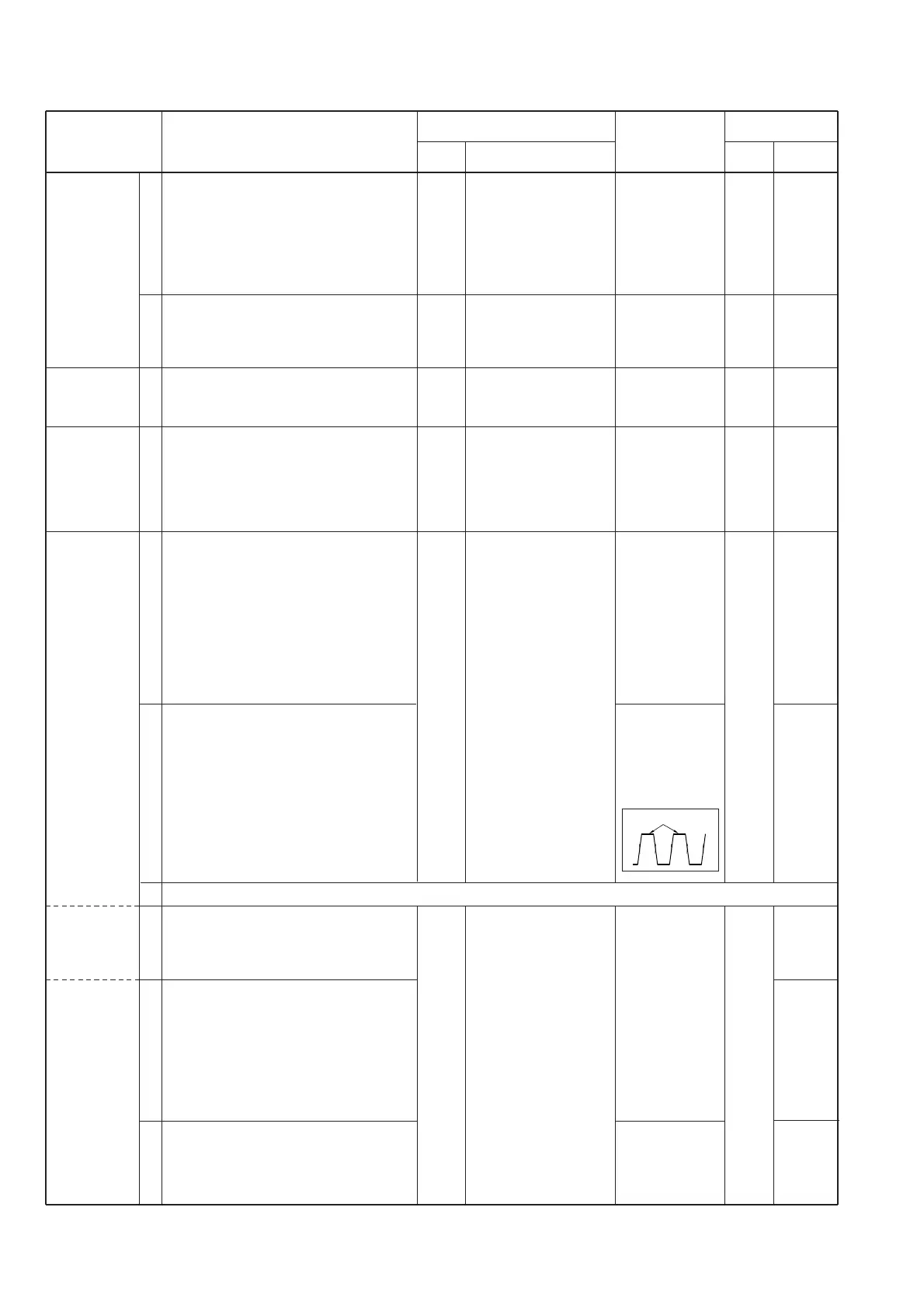
Minimum devia-
tion, and a con-
nected oscillo-
scope to the FM
deviation meter
as shown below.
#03: ±3.0 kHz
#04: ±1.5 kHz
#03:
±3.0–5.0 kHz
#04:
±1.5–2.5 kHz
1
2
1
1
1
2
3
4
5
6
• Operating freq. : 415.000 MHz
• Apply DC voltage : 13.8 V
[VOLUME] : Max. CCW
[SQUELCH] : Max. CW
• Connect an RF power meter or termi-
nator to the [TX ANT] connector.
• Transmitting
• [LOCAL INHIBIT] switch : ON
• Receiving freq. : 415.050 MHz
[VOLUME]
: “11 o’clock” position
• Receiving
• Operating freq. :415.000 MHz
• Transmitting
• [LOCAL INHIBIT] switch : ON
• Operating freq. :415.000 MHz
• Apply DC voltage : 13.8 V
[VOLUME] : Max. CCW
[SQUELCH] : Max. CW
• Transmitting
• [LOCAL INHIBIT] switch : ON
• Set an FM deviation meter as :
HPF : OFF
LPF : 20 kHz
De-emphasis : OFF
Detector : (P–P)/2
• Disconnect P1 from J5 on the TX
unit, connect an audio generator to J5
and set as : 1 kHz/ 1 V
• Transmitting
• Set an AG as : 50 Hz/ 1 V
• Transmitting
• Connect an AG to [MIC] connector
and set as : 1 kHz/ 4 mV
• Transmitting
• [LOCAL INHIBIT] switch : OFF
• Connect an SSG to the [RX ANT]
connector and set as:
Level : 1 mV*
(60 dBµ)
Deviation : ±3 kHz
Modulation : 1 kHz
• Receiving
•Set an SSG as
Deviation : ±5.0 kHz [#03]
: ±2.5 kHz [#04]
• Receiving
PLL LOCK
VOLTAGE
REFERENCE
FREQUENCY
OUTPUT
POWER
DEVIATION
(MAXIMUM)
(MICROPHONE)
(REPEATER)
TX
RX
Rear
panel
Rear
panel
Rear
panel
Rear
panel
Connect a digital multi-
meter or an oscillo-
scope to check point
[LV].
Connect a digital multi-
meter or an oscillo-
scope to check point
[LV].
Loosely couple a fre-
quency counter to the
[TX ANT] connector.
Connect an RF power
meter or a terminator
to the [TX ANT] con-
nector.
Connect an FM devia-
tion meter to the
[TX ANT] connector
through an attenuator.
Connect an FM devia-
tion meter to the
[TX ANT] connector
through an attenuator.
TX
RX
TX
PA
TX
LOGIC
L3
L16
R38
(F–SET)
R16
(Hi)
R50
(MOD)
R43
(R–MOD)
R61
(MIC)
R47
(MOD)
Verify
ADJUSTMENT ADJUSTMENT CONDITIONS
UNIT LOCATION
VALUE
UNIT ADJUST
MEASUREMENT ADJUSTMENT