5-4
4-2 TRANSMIT ADJUSTMENTS (continued)
Select an adjustment item using [MONI]/[QUICK], and then set the adjustment value as specified using [DIAL].
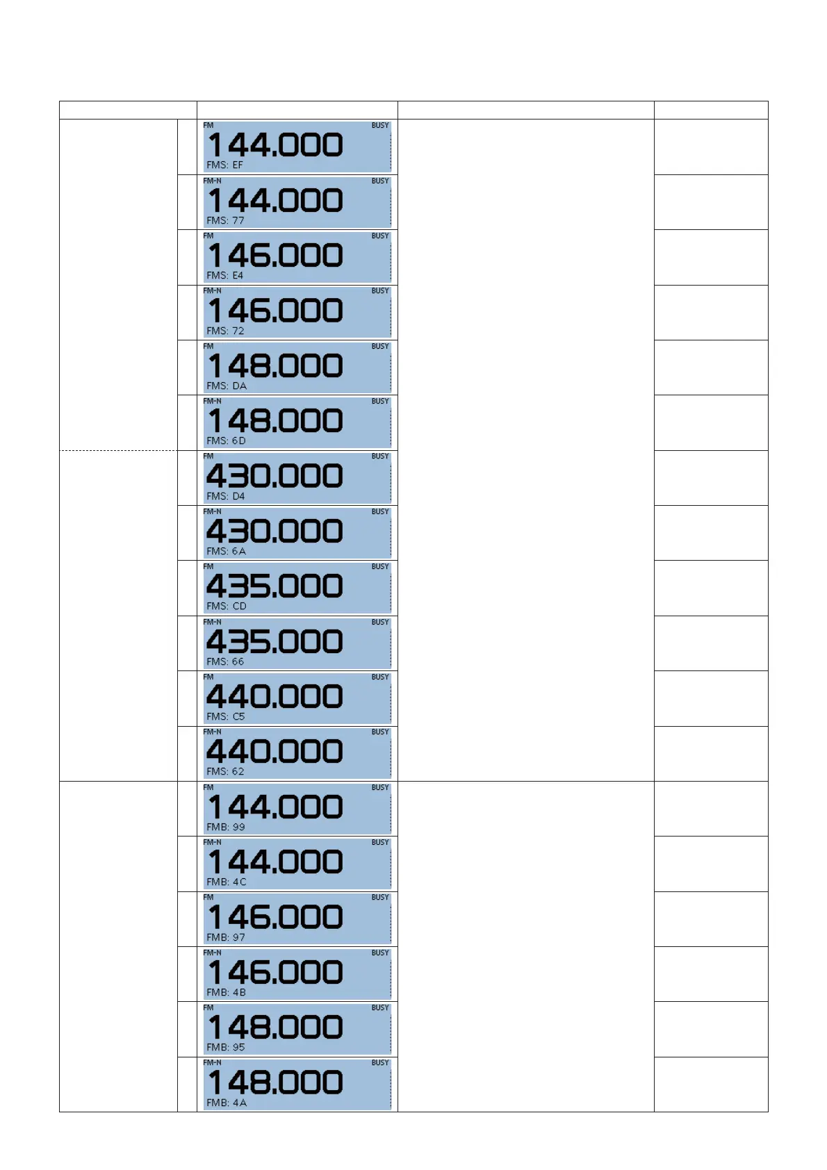
ADJUSTMENT ITEM TRANSCEIVER'S DISPLAY CONDITION VALUE
FM DEVIATION
VHF
14
• Connect the test equipment to the antenna
connector through the attenuator, and set
as shown below:
HPF: OFF
LPF: 20 kHz
De-emphasis: OFF
Detector: (P−P)/2
• Connect the test equipment to [MIC], and
set as shown below:
Frequency: 1 kHz
Wave form: Sine wave
Output level: 80 mV rms (USA)
20 mV rms (other than USA)
• Transmit.
±4.2 kHz
15
±2.1 kHz
16
±4.2 kHz
17
±2.1 kHz
18
±4.2 kHz
19
±2.1 kHz
UHF
20
±4.2 kHz
21
±2.1 kHz
22
±4.2 kHz
23
±2.1 kHz
24
±4.2 kHz
25
±2.1 kHz
FM DEVIATION
BALANCE
VHF
26
• Connect the test equipment to the antenna
connector through the attenuator, and set
as shown below:
HPF: OFF
LPF: 20 kHz
De-emphasis: OFF
Detector: (P−P)/2
• No audio is applied to [MIC].
• Transmit.
±4.7 kHz
27
±2.35 kHz
28
±4.7 kHz
29
±2.35 kHz
30
±4.7 kHz
31
±2.35 kHz
NOTE:
The displayed adjustment frequency is only an example, and the frequency will differ depending on the transceiver version.

 Loading...


