Cha
ter 1 Introduction
ET-7000 AIO User Manual, Apr. 2009, V1.04, EMH-011-104----------31
1.5.2. Connecting the Hardware
Step 1: Connect the Ethernet cable between the ET-7000 and the Host PC. Please
refer to the Ethernet cable wiring section at the next page.
Step 2: Apply the power (+Vs, GND) in a range from 10 to 30 V
DC
to the ET-7000.
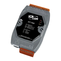
Step 3: Check that the “RUN” LED (L1) on the ET-7000 is periodically ON for 0.5
seconds and then OFF for 0.5 seconds.
Notes:
In ET-7000 series modules, V+ is connected to Pin 8 of the J2 connector, and GND is
connected to Pin 9 of the J2 connector.
Ethernet
Power supply
Host PC
 Loading...