440 01 2021 01
34
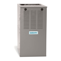
MANIFOLD PRESSURE AND ORIFICE SIZE FOR HIGH ALTITUDE APPLICATIONS
NAT URAL GAS MANIFOLD PRESSURE (²
²²
² w.c.)
MEAN ELEVATION FEET ABOVE SEA LEVEL
HEATING
0 to 2000 2001 to 3000 3001 to 4000 4001 to 5000 5001 to 6000 6001 to 7000 7001 to 8000
VALUE at
Orifice
MnfldPressure Orifice
MnfldPressure Orifice
MnfldPressure Orifice
MnfldPressure Orifice
MnfldPressure Orifice
MnfldPressure Orifice
MnfldPressure
BTU/CU.FT.
No.
Hi Lo
No.
Hi Lo
No.
Hi Lo
No.
Hi Lo
No.
Hi Lo
No.
Hi Lo
No.
Hi Lo
700 -- -- -- -- -- -- -- -- -- -- -- -- -- -- -- -- -- -- -- -- -- -- -- -- -- -- -- -- -- -- -- -- -- -- -- -- 41 3.7 1.8
725 -- -- -- -- -- -- -- -- -- -- -- -- -- -- -- -- -- -- -- -- -- -- -- -- -- -- -- -- -- -- 41 3.7 1.8 41 3.4 1.7
750 -- -- -- -- -- -- -- -- -- -- -- -- -- -- -- -- -- -- -- -- -- -- -- -- -- -- -- -- -- -- 41 3.5 1.7 42 3.6 1.7
775 -- -- -- -- -- -- -- -- -- -- -- -- -- -- -- -- -- -- -- -- -- -- -- -- 41 3.6 1.7 42 3.6 1.8 42 3.3 1.6
800 -- -- -- -- -- -- -- -- -- -- -- -- -- -- -- -- -- -- 41 3.6 1.8 42 3.7 1.8 42 3.4 1.7 42 3.1 1.5
825 -- -- -- -- -- -- -- -- -- -- -- -- 41 3.7 1.8 41 3.4 1.7 42 3.5 1.7 42 3.2 1.6 43 3.6 1.8
850 -- -- -- -- -- -- -- -- -- -- -- -- 41 3.5 1.7 42 3.6 1.7 42 3.3 1.6 43 3.7 1.8 43 3.4 1.7
875 -- -- -- -- -- -- 41 3.6 1.7 42 3.6 1.8 42 3.4 1.6 42 3.1 1.5 43 3.5 1.7 43 3.2 1.6
900 -- -- -- -- -- -- 42 3.7 1.8 42 3.4 1.7 42 3.2 1.6 43 3.6 1.7 43 3.3 1.6 44 3.5 1.7
925 41 3.7 1.8 42 3.5 1.7 42 3.3 1.6 43 3.7 1.8 43 3.4 1.7 43 3.1 1.5 44 3.3 1.6
950 41 3.5 1.7 42 3.3 1.6 42 3.1 1.5 43 3.5 1.7 43 3.2 1.6 44 3.4 1.7 44 3.1 1.5
975 42 3.7 1.8 42 3.2 1.6 43 3.6 1.8 43 3.3 1.6 44 3.5 1.7 44 3.2 1.6 45 3.6 1.7
1000 42 3.5 1.7 43 3.7 1.8 43 3.4 1.7 43 3.1 1.5 44 3.3 1.6 45 3.7 1.8 45 3.4 1.7
1050 42 3.2 1.6 43 3.3 1.6 43 3.1 1.5 44 3.3 1.6 45 3.6 1.8 -- -- -- -- -- -- -- -- -- -- -- --
1100 43 3.6 1.7 44 3.5 1.7 44 3.2 1.6 45 3.6 1.8 -- -- -- -- -- -- -- -- -- -- -- -- -- -- -- -- -- --
NOTE: Natural gas data is based on 0.60 specific gravity. For fuels with different specific gravity consult the National Fuel Gas Code ANSI
Z223.1--2002/NFPA 54--2002 or National Standard of Canada, Natural Gas and Propane Installation Code CSA B149.1--05.
Table 7 LPG or PROPANE GAS MANIFOLD PRESSURE (²
²²
² w.c.)
MEAN ELEVATION FEET ABOVE SEA LEVEL
HEATING VALUE
0 to 2000 2001 to 3000 3001 to 3999 4001 to 5000 5001 to 6000 6001 to 7000 7001 to 8000
at
LTITUDE
BTU/CU. FT.
Hi Lo Hi Lo Hi Lo Hi Lo Hi Lo Hi Lo Hi Lo
2500 10.0 4.9 10.0 4.9 9.0 4.4 10.0 4.9 9.4 4.6 8.5 4.2 10 4.9
Orifice Size #54 #54 #54 #55 #55 #55 #56
NOTE: Propane data is based on 1.53 specific gravity. For fuels with different specific gravity consult the National Fuel Gas Code ANSI
Z223.1--2002/NFPA 54--2002 or National Standard of Canada, Natural Gas and Propane Installation Code CSA B149.1--05.
NOTE: The derating of these furnaces at 2% (Natural Gas) and 4% (Propane Gas) has been tested and design--certified by CSA.
In Canada, the input rating must be derated 5% (Natural Gas) and 10% (Propane Gas) for altitudes of 2,000 to 4,500 above sea level. Use
the 2001 to 3000 column in Table 6 and Table 7.
The burner orifice part nos. a re as follows:
Orifice #41 1096942 Orifice #42 1011351
Orifice #43 1011377 Orifice #44 1011352
Orifice #45 1011353 Orifice #54 1011376
Orifice #55 1011354 Orifice #56 1011355
Changing Orifices for High Altitude
ELECTRICAL SHOCK, FIRE OR EXPLOSION
HAZARD.
Failure to properly install orifices could result in
death, personal injury and/or property damage.
Turn OFF electric power (at disconnect) and gas
supply (at manual valve in gas line) when installing
orifices. Installation of orifices requires a qualified
service technician.
!
WARNING
NOTE: Main burner orifices can be changed for high altitudes.
1. Disconnect gas line from gas valve.
2. Remove manifold from furnace.
3. Remove the orifices from the manifold and replace them
with properly sized orifices.
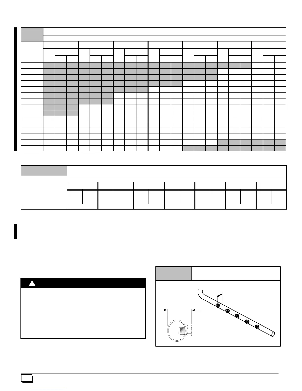
4. Tighten orifices so it is seated and gas tight. (See
Figure 37)
Figure 37
Changing Orifices
1
1
/
8
²
to 1
3
/
16
²
Measurefromfaceofori-
fice to thebacksideofthe
manifold.
5. Reinstall manifold. Ensure burners do NOT bind on new ori -
fices.
 Loading...