SERVICE AND TECHNICAL SUPPORT MANUAL Gas Furnace: (F/G)9MVE
Specifications subject to change without notice.
440 04 4801 03 7
e. Move setup SW1—2 on furnace control to ON
position to lock furnace in low−heat operation. (See
Figure 4 and Figure 5)
f. Manually close blower door switch.
g. Jumper R and W/W1 thermostat connections on
control to start furnace. (See Figure 4)
h. Remove regulator adjustment cap from low heat gas
valve pressure regulator (See Figure 3) and turn
low−heat adjusting screw (3/16 or smaller flat−tipped
screwdriver) counterclockwise (out) to decrease input
rate or clockwise (in) to increase input rate.
NOTICE
DO NOT set low−heat manifold pressure less than 1.3−in. w.c.
(324 Pa) or more than 1.7−in. w.c. (423 Pa) for natural gas. If
manifold pressure is outside this range, change main burner
orifices.
i. Install low−heat regulator adjustment cap.
j. Move setup switch SW1−2 to OFF position after
completing low−heat adjustment.
k. Leave manometer or similar device connected and
proceed to Step 2.
2. Adjust manifold pressure to obtain high fire input rate.
(See Figure 3)
a. Jumper R to W/W1 and W2 thermostat connections
on furnace control. This keeps furnace locked in
high−heat operation.
b. Remove regulator adjustment cap from high−heat
gas valve pressure regulator (See Figure 3) and turn
high heat adjusting screw (3/16−in. or smaller
flat−tipped screwdriver) counterclockwise (out) to
decrease input rate or clockwise (in) to increase input
rate.
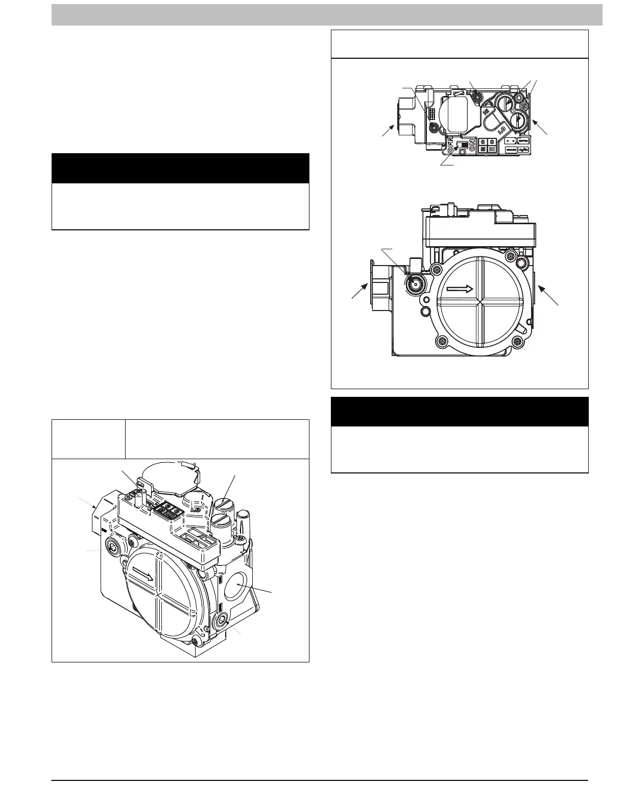
Figure 3
Redundant Automatic Gas Control
Valve (2−Stage) without Tower
Pressure Ports
ON/OFF Switch
Regulator Seal Cap
Regulator Adjustment
Regulator Seal Cap under Cap
1/2” NPT Outlet
1/8” NPT Manifold
Pressure Tap
1/8” NPT Inlet
Pressure Tap
1/2” NPT Inlet
A11152
Automatic Gas Valve (Two−Stage) with Tower
Pressure Ports
INLET PRESSURE TAP
SET SCREW: 3/32” HEX HEAD
ACCEPTS 5/16” HOSE
CONNECTION
ON/OFF SWITCH
MANIFOLD PRESSURE TAP SET SCREW:
3/32” HEX HEAD ACCEPTS
5/16” HOSE CONNECTION
REGULATOR SEAL CAP
(REGULAR ADJ. UNDER CAP)
OUTP
1/2” NPT
INLET
1/2” NPT
OUTLET
Representative drawing only, some models may vary in appearance.
L170117
L170132
1/8” NPT
INLET
PRESSURE
TAP
INP
1/2” NPT
INLET
1/2” NPT
OUTLET
Representative drawing only, some models may vary in appearance.
NOTICE
DO NOT set high−heat manifold pressure less than 3.2−in. w.c.
(797 Pa) or more than 3.8 in. w.c. (947 Pa) for natural gas. If
required manifold pressure is outside this range, change main
burner orifices to obtain manifold pressure in this range.
c. When correct input is obtained, replace caps that
conceal gas valve regulator adjustment screws. Main
burner flame should be clear blue, almost
transparent. (See Figure 14)
d. Remove jumpers R to W/W1 and R to W2.
3. Verify natural gas input rate by clocking meter.
NOTE: Contact your HVAC distributor or gas supplier for metric
gas meter Tables, if required.
a. Turn off all other gas appliances and pilots served by
the meter.
b. Move setup switch SW1−2 to ON position. This
keeps furnace locked in low−heat operation when
only W/W1 is energized.
c. Jumper R to W/W1.
d. Run furnace for 3 minutes in low−heat operation.
 Loading...