SERVICE AND TECHNICAL SUPPORT MANUAL Gas Furnace: (F/G)9MVE
Specifications subject to change without notice.
8 440 04 4801 03
e. Measure time (in sec) for gas meter to complete 1
revolution and note reading. The 2 or 5 cubic feet dial
provides a more accurate measurement of gas flow.
f. Refer to Table 2 for cubic ft. of gas per hr.
g. Multiply gas rate cu ft./hr by heating value (Btuh/cu
ft.) to obtain input.
h. If clocked rate does not match required input from
Step 1, increase manifold pressure to increase input
or decrease manifold pressure to decrease input.
Repeat steps b through e until correct low−heat input
is achieved. Re−install low heat regulator seal cap on
gas valve.
i. Jumper R to W/W1, and W2. This keeps furnace
locked in high−heat operation when both W/W1 and
W2 are energized.
j. Repeat items (d) through (h) for high−heat operation,
repeating Step 2 and adjusting the high−heat regular
screw, as required.
4. Restore furnace to normal operating condition.
a. Turn gas valve On/Off switch to OFF.
b. Remove water column manometer or similar device
from manifold pressure tap.
FIRE HAZARD
Failure to follow this warning could result in personal injury,
death, and/or property damage.
Manifold pressure tap set screw must be tightened or
1/8−in. NPT pipe plug must be installed to prevent gas
leaks.
!
WARNING
c. Tighten set screw on manifold tower pressure tap
with 3/32−in. hex wrench, or if 1/8−in. NPT plug was
removed, apply pipe dope sparingly to end of plug
and re−install in the gas valve.
d. Turn gas valve On/Off switch to ON.
e. Move setup SW1−2 on furnace control to position
required for attached thermostat (OFF for
single−stage thermostats, ON for two−stage
thermostats).
f. Check for gas leaks and verify furnace operation.
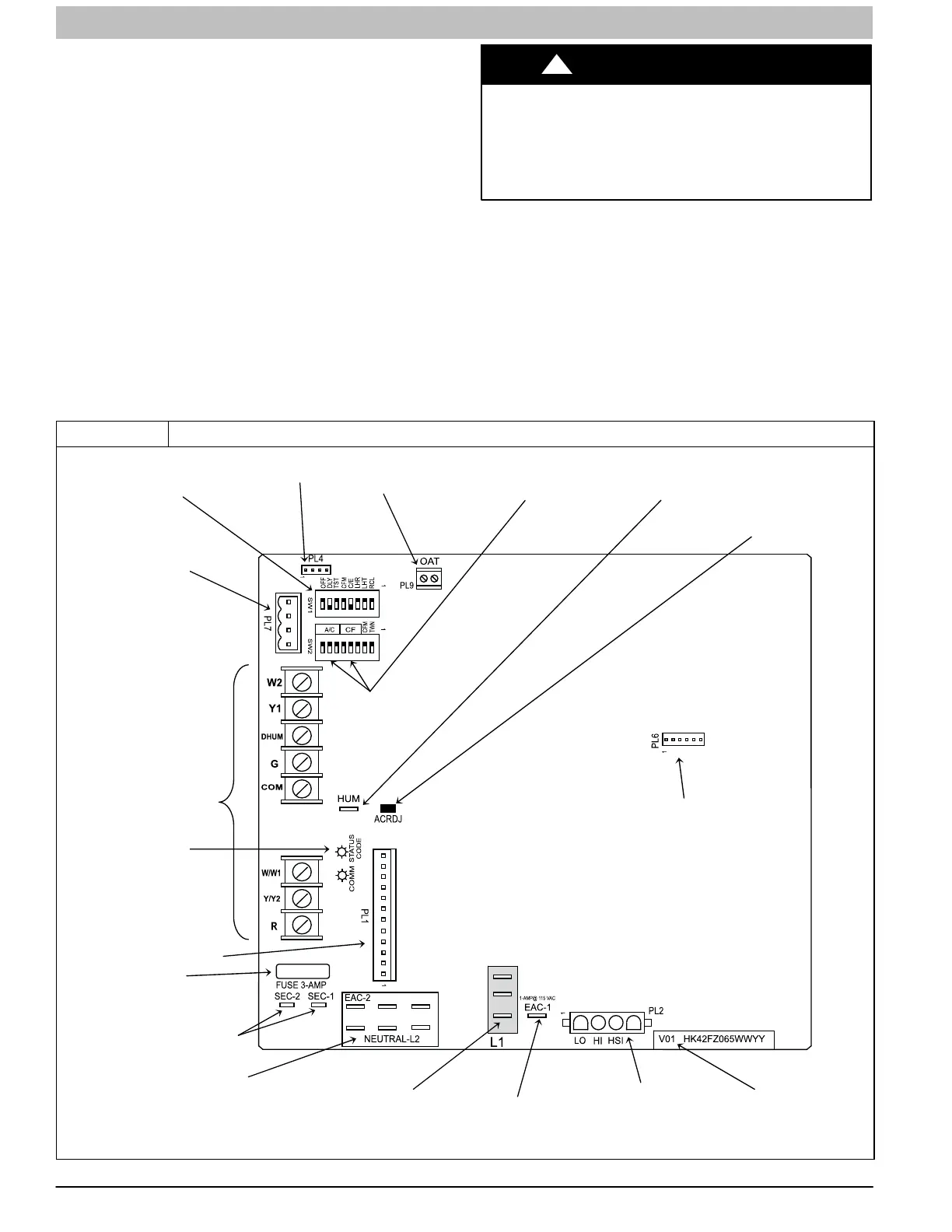
Figure 4 Example of Variable Speed Furnace Control for Variable Speed ECM Blower Motor
L14F003
24-V THERMOSTAT
TERMINALS
PL2 – HOT SURFACE
IGNITER & INDUCER
MOTOR CONNECTOR
115-VAC (L2) NEUTRAL
CONNECTIONS
115-VAC (L1) LINE
VOLTAGE CONNECTIONS
EAC-1 TERMINAL
115-VAC 1.0 AMP MAX.
PL1 – LOW VOLTAGE MAIN
HARNESS CONNECTOR
TRANSFORMER 24-VAC
CONNECTIONS
3-AMP FUSE
STATUS AND COMM
LED LIGHTS
SW1 SETUP
SWITCHES AND
BLOWER OFF-
DELAY
MODEL PLUG
CONNECTOR
COMMUNICATION
CONNECTOR
AIR CONDITIONING (A/C) &
CONTINUOUS FAN (CF)
AIRFLOW SETUP SWITCHES
OUTDOOR
AIR TEMP
CONNECTOR
HUMIDIFIER
TERMINAL (24-VAC
0.5 AMP MAX.)
ACRDJ – AIR
CONDITIONING
RELAY DISABLE
JUMPER
FLASH
UPGRADE
CONNECTOR
(FACTORY
ONLY)
SOFTWARE
VERSION
 Loading...