SERVICE AND TECHNICAL SUPPORT MANUAL Gas Furnace: (F/G)9MVE
Specifications subject to change without notice.
22 440 04 4801 03
3. Align the edges of the one-piece burner with the slots in
the burner assembly and slide the burners forward until
they are fully seated in the burner assembly.
4. Align the orifices in the manifold assembly with the
support rings on the end of the burner.
5. Insert the orifices in the support rings of the burners.
NOTE: If manifold does not fit flush against the burner, do not
force the manifold on the burner assembly. The burners are not
fully seated forward in the burner assembly. Remove the
manifold and check burner positioning in the burner assembly
assembly before re-installing the manifold.
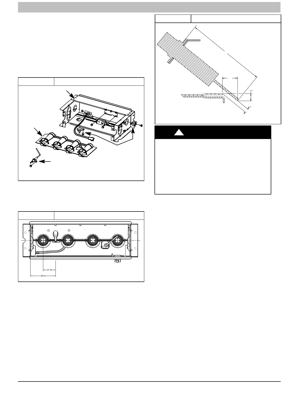
Figure 10 Burner Assembly
BURNER ASSY
FLAME SENSOR
(
BELOW BURNER)
FLAME ROLL−OUT SWITCH
BURNER SUPT. ASSY
L11F064
Representative drawing only, some models may vary in appearance.
6. Attach the green/yellow wire and ground terminal to one
of the manifold mounting screws.
7. Install the remaining manifold mounting screws.
8. Check the igniter alignment. See Figure 10, Figure 11
and Figure 12.
Figure 11 Igniter Position − Top View
A11271
1-1/4-in.
2-1/2-in.
9. Attach the wires to the roll-out switches.
10. Align the burner assembly with the openings in the
primary cell inlet panel and attach the burner assembly to
the cell panel.
11. Connect the wire for the flame sensor.
12. Connect the wire for the Hot Surface Igniter.
NOTE: Use propane-resistant pipe dope to prevent leaks. Do
not use Teflon tape.
13. Install the gas pipe to the gas valve.
Figure 12 Igniter Position − Side View
L12F041
2ïin.
2.5 mm
3/8ïin.
3/16ïin.
+0.8
ï1.5 mm
50 mm
9.6 mm
4.6 mm
1/10ïin.
+ 1/32
ï 1/16ïin.
FIRE OR EXPLOSION HAZARD
Failure to follow this warning could result in personal
injury, death, and/or property damage.
Never purge a gas line into a combustion chamber.
Never test for gas leaks with an open flame. Use a
commercially available soap solution made
specifically for the detection of leaks to check all
connections. A fire or explosion may result causing
property damage, personal injury or loss of life.
!
WARNING
14. Check for gas leaks with a commercially available soap
solution made specifically for the detection of leaks.
15. Turn gas on at electric switch on gas valve and at
external shut-off or meter
16. Turn power on at external disconnect, fuse or circuit
breaker.
17. Run the furnace through two complete heating cycles to
check for proper operation
18. Install control door when complete.
Servicing Hot Surface Igniter
The igniter does NOT require annual inspection. Check igniter
resistance before removal. Refer to Figure 10, Figure 11 and
Figure 12.
1. Turn off gas and electrical supplies to furnace.
2. Remove control door.
3. Disconnect igniter wire connection.
4. Check igniter resistance. Igniter resistance is affected by
temperature. Only check resistance when the igniter is at
room temperature.
a. Using an ohm meter, check resistance across both
igniter leads in connector.
b. Cold reading should be between 40 ohms and 70
ohms.
 Loading...