SERVICE AND TECHNICAL SUPPORT MANUAL Gas Furnace: (F/G)9MVE
Specifications subject to change without notice.
440 04 4801 03 11
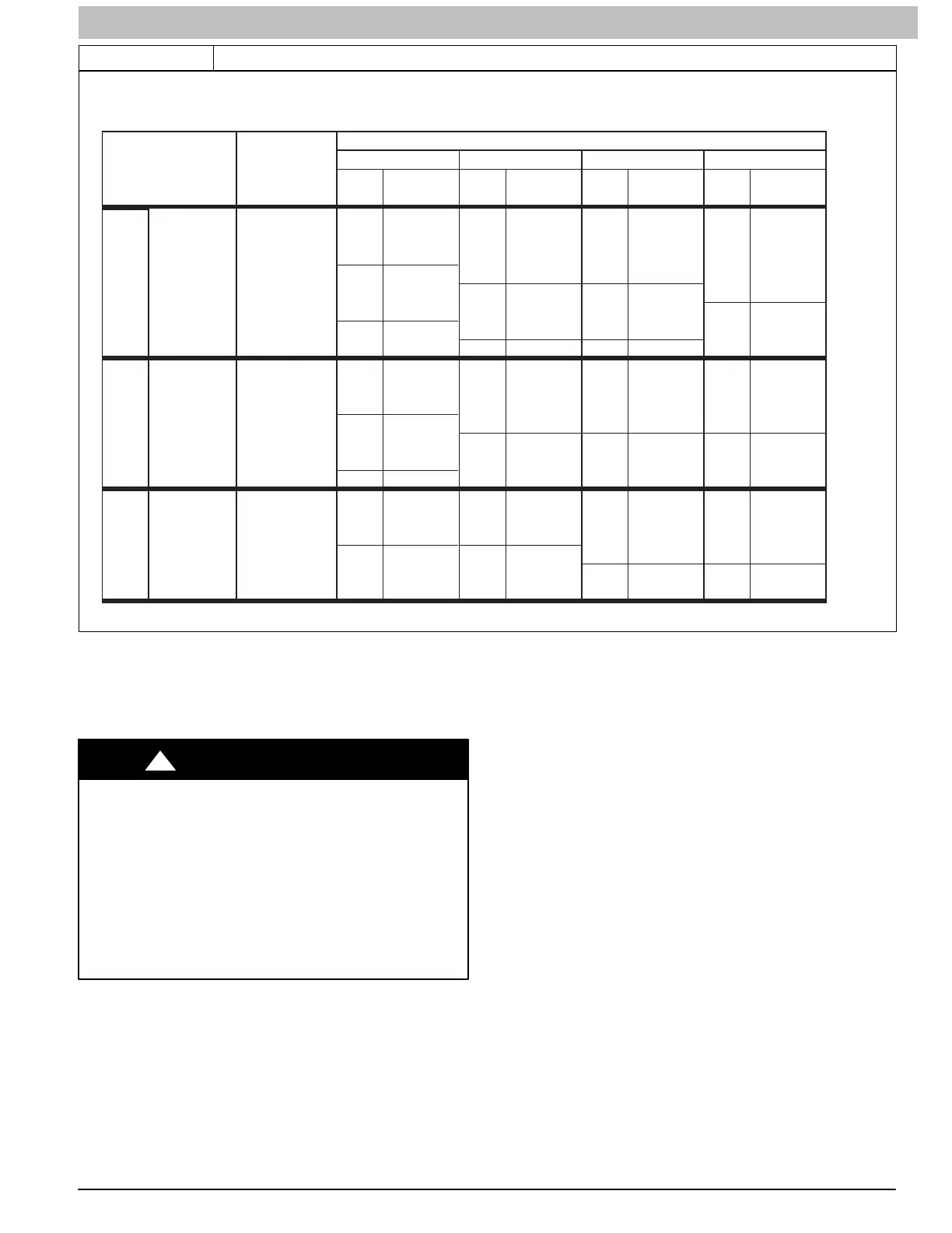
Table 3 (cont.) Orifice Size and Manifold Pressure (in. w.c.) for Gas Input Rate − Two−Stage
SAGLARUTANFOYTIVARGCIFICEPSSAG.GVA
HEATVALUE0.580.600.620.64
AT ALTITUDE Orifice Mnfld Press Orifice Mnfld Press Orifice Mnfld Press Orifice Mnfld Press
(Btu/cu ft) No. High/Low No. High/Low No. High/Low No. High/Low
TWO-STAGE FURNACE
(TABULATED DATA BASED ON 20,000 BTUH HIGH-HEAT / 13,000 BTUH LOW-HEAT PER BURNER,
DERATED 2%/1000 FT (305M) ABOVE SEA LEVEL)
ALTITUDE
RANGE
ft (m)
650 42 3.4 / 1.4 42 3.5 / 1.5 42 3.6 / 1.5 42 3.7 / 1.6
7001 675 43 3.8 / 1.6 42 3.2 / 1.4 42 3.3 / 1.4 42 3.4 / 1.5
(2134) 700 43 3.5 / 1.5 43 3.7 / 1.5 43 3.8 / 1.6 42 3.2 / 1.4
725 44 3.8 / 1.6 43 3.4 / 1.4 43 3.5 / 1.5 43 3.6 / 1.5
750 44 3.5 / 1.5 44 3.7 / 1.5 44 3.8 / 1.6 43 3.4 / 1.4
8000 775 44 3.3 / 1.4 44 3.4 / 1.4 44 3.5 / 1.5 44 3.7 / 1.5
(2438) 800 45 3.8 / 1.6 44 3.2 / 1.4 44 3.3 / 1.4 44 3.4 / 1.4
825 46 3.7 / 1.6 46 3.8 / 1.6 45 3.8 / 1.6 44 3.2 / 1.4
625 42 3.4 / 1.4 42 3.5 / 1.5 42 3.6 / 1.5 42 3.7 / 1.6
8001 650 43 3.8 / 1.6 42 3.2 / 1.4 42 3.3 / 1.4 42 3.4 / 1.4
(2439) 675 43 3.5 / 1.5 43 3.6 / 1.5 43 3.7 / 1.6 42 3.2 / 1.3
700 44 3.7 / 1.6 43 3.4 / 1.4 43 3.5 / 1.5 43 3.6 / 1.5
725 44 3.5 / 1.5 44 3.6 / 1.5 44 3.7 / 1.6 44 3.8 / 1.6
9000 750 44 3.3 / 1.4 44 3.4 / 1.4 44 3.5 / 1.5 44 3.6 / 1.5
(2743) 775 45 3.7 / 1.6 44 3.2 / 1.3 44 3.3 / 1.4 44 3.4 / 1.4
9001 600 42 3.3 / 1.4 42 3.4 / 1.5 42 3.6 / 1.5 42 3.7 / 1.6
(2744) 625 43 3.7 / 1.6 42 3.2 / 1.3 42 3.3 / 1.4 42 3.4 / 1.4
650 43 3.5 / 1.5 43 3.6 / 1.5 43 3.7 / 1.6 43 3.8 / 1.6
675 44 3.7 / 1.6 44 3.8 / 1.6 43 3.4 / 1.4 43 3.5 / 1.5
10000 700 44 3.4 / 1.4 44 3.5 / 1.5 44 3.7 / 1.5 44 3.8 / 1.6
(3048) 725 44 3.2 / 1.3 44 3.3 / 1.4 44 3.4 / 1.4 44 3.5 / 1.5
* Orifice numbers shown in BOLD are factory-installed.
to
to
to
U.S.A. OnlyU.S.A. Only U.S.A. Only
A11252B
Adjust Temperature Rise
NOTE: Blower door must be installed when taking temperature
rise reading. Leaving blower door off will result in incorrect
temperature measurements, due to possible changes in duct
static pressure and airflow.
FURNACE DAMAGE HAZARD
Failure to follow this caution may result in:
S Overheating the heat exchangers or condensing
flue gases in heat exchanger areas not designed
for condensate.
S Shortened furnace life.
S Component damage.
Temperature rise must be within limits specified on furnace
rating plate. Recommended operation is at midpoint of rise
range or slightly above.
CAUTION
!
Furnace must operate within ranges of temperature rise
specified on the furnace rating plate.
When setup switch SW1−4 is ON, operation will be near the
high end of the rise range for improved comfort.
Determine air temperature rise as follows:
1. Place thermometers in return and supply ducts as near
furnace as possible. Be sure thermometers do not see
heat exchanger so that radiant heat does not affect
readings. This practice is particularly important with
straight−run ducts.
2. When thermometer readings stabilize, subtract return−air
temperature from supply−air temperature to determine air
temperature rise.
NOTE: Temperature rise can be determined for low−heat
operation by locking the furnace in each mode of operation.
The mode of operation is based on the position of set up switch
SW1−2 on the furnace control board.
This furnace is capable of automatically providing proper
airflow to maintain the temperature rise within the range
specified on furnace rating plate. If temperature rise is outside
this range, proceed as follows:
a. Check gas input for low− and high−heat operation.
b. Check derate for altitude if applicable.
c. Check all return and supply ducts for excessive
restrictions causing static pressure greater than
0.5−in. w.c.
d. Ensure Low Heat Rise Adjust switch SW1−3 on
furnace control is in ON position when a bypass
humidifier is used. (See Figure 4 for switch location.)
e. Check Troubleshooting Guide for Variable−Speed
Condensing Furnaces.
To lock the furnace in Low Heat:
1. Turn SW1-2 ON at the furnace control. Set up switch
2. Connect a jumper across R and W/W1 at the thermostat
terminals at the furnace control.
3. Allow the burners to ignite and the blower to turn on.
4. Allow the supply temperature to stabilize and verify the
proper rise range.
If the temperature rise is too high or too low in Low Heat:
 Loading...