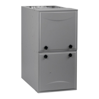
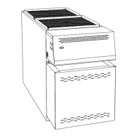
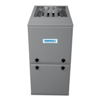
SERVICE AND TECHNICAL SUPPORT MANUAL Gas Furnace: (F/G)9MVE
Specifications subject to change without notice.
12 440 04 4801 03
1. Remove jumpers from R and W/W1.
2. Wait until the blower off delay is completed.
3. Turn 115 VAC power off.
4. Check the position of Set up switch SW1-3. When set to
ON, airflow is raised 18% for Low Heat. Factory default
position is OFF.
5. Turn 115 VAC power on.MN7A
6. Re--check Low Heat Temperature Rise
To lock the furnace in High Heat:
1. Connect a jumper across R and W/W1 and W2 at the
thermostat terminals at the furnace control.
2. Allow the burners to ignite and the blower to turn on.
3. Allow the supply temperature to stabilize and verify the
proper rise range.
If the temperature rise is too high or too low in High Heat:
1. Remove jumpers from R and W/W1 and W2.
2. Wait until the blower off delay is completed.
3. Turn 115 VAC power off.
4. Check the position of Set up switch SW1-4. When set to
OFF and SW1-3 is set to OFF, airflow is raised 7% for
Low Heat and 10% for High Heat. Factory default
position is ON. If SW1-3 is ON and SW1-4 is OFF, airflow
is raised 18% for Low Heat and 10% for High Heat
5. Turn 115 VAC power on.
6. Re-check High Heat Temperature Rise.
After the temperature rise has been verified:
1. Remove jumpers from thermostat terminals.
2. Allow the blower off delay to complete.
3. Turn Set up switches SW1-2 to the desired position.
4. Proceed to “Adjust Blower Off Delay” or install blower
door if complete
.
FIRE HAZARD
Failure to follow this warning could result in personal injury,
death, and/or property damage.
Reinstall manifold pressure tap plug in gas valve to
prevent gas leak.
!
WARNING
FURNACE OVERHEATING HAZARD
Failure to follow this caution may result in reduced furnace
life.
Recheck temperature rise. It must be within limits specified
on the rating plate. Recommended operation is at the
mid−point of rise range or slightly above.
CAUTION
!
Adjust Blower Off Delay (Heat Mode)
a. Remove blower door if installed.
b. Turn Dip switch SW1−7 or SW1−8 ON or OFF for
desired blower off delay. (See Table 4 and Figure 4,
Figure 5)
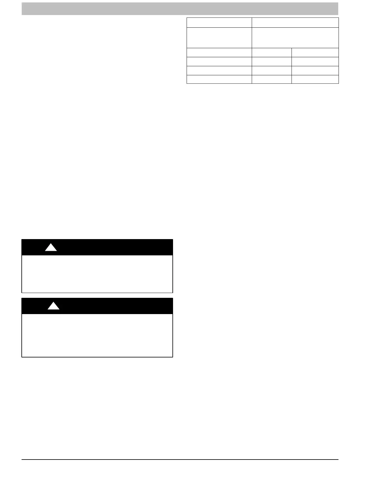
Table 4 Blower Speed Taps
DESIRED HEATING MODE
BLOWER OFF DELAY
(SEC.)
SETUP SWITCH (SW1-7 and -8)
POSITION
90 OFF OFF
120 ON OFF
150 OFF ON
180 ON ON
Adjust Cooling Airflow − High−Speed and
Low−Speed Cooling
The ECM blower can be adjusted for a range of airflows for
low−speed or high−speed cooling. See Table 5−Air Delivery −
CFM (with Filter) and Figure 5. Furnace Setup Switches and
Descriptions. Depending on the model size, the cooling airflow
can be adjusted from 1.5 tons to 6 tons of nominal cooling
based on 350 CFM ton.
NOTE: 6 ton airflow will truncate at 2200 CFM on applicable
models.
The high−speed or single−speed cooling airflow is adjusted by
turning setup switches SW2−6, SW2−7 and SW2−8 either ON
or OFF. Select the required airflow from Table 5. Table 5 is
based on 350 CFM per ton. For other CFM per ton setup switch
selections, see Figure 4, Figure 5 and Figure 16.
The Continuous Fan airflow selection via setup switches
SW2−3, SW2−4 and SW2−5 is also the airflow for low−speed
cooling when the furnace is used with a two−speed cooling or
heat pump unit. Adjust the Continuous Fan CFM setup
switches SW2−3, SW2−4 and SW2−5 to match the airflow
required for low−speed cooling. Select the required airflow from
Table 5 and Figure 5.
NOTE: The airflow selected via SW2−3, SW2−4 and SW2−5
(low−speed cooling airflow) cannot exceed the airflow selected
via SW2−6, SW2−7 and SW2−8 (high−speed cooling airflow).
For other CFM per ton setup switch selections, see Figure 4
and Figure 5.
For a complete explanation of cooling airflow, refer to the
section titled “Sequence of Operation.”
Adjust Continuous Fan Airflow/Low Speed
Cooling Airflow
NOTE: When the furnace is used with a two−speed cooling or
heat pump unit, the airflow selected for Continuous Fan via
setup switch SW2−3, SW2−4 and SW2−5 will also be the
airflow used for low−speed cooling, and vice versa.
NOTE: When the furnace is used with a two−speed cooling or
heat pump unit, adjust the Continuous Fan CFM setup
switches SW2−3, SW2−4 and SW2−5 to match the airflow
required for low−speed cooling.
Select the required Continuous Fan airflow using setup
switches SW2−3, SW2−4 and SW2−5 as shown in Figure 5
and Table 5.
 Loading...