42 440 01 4300 00
Specifications subject to change without notice.
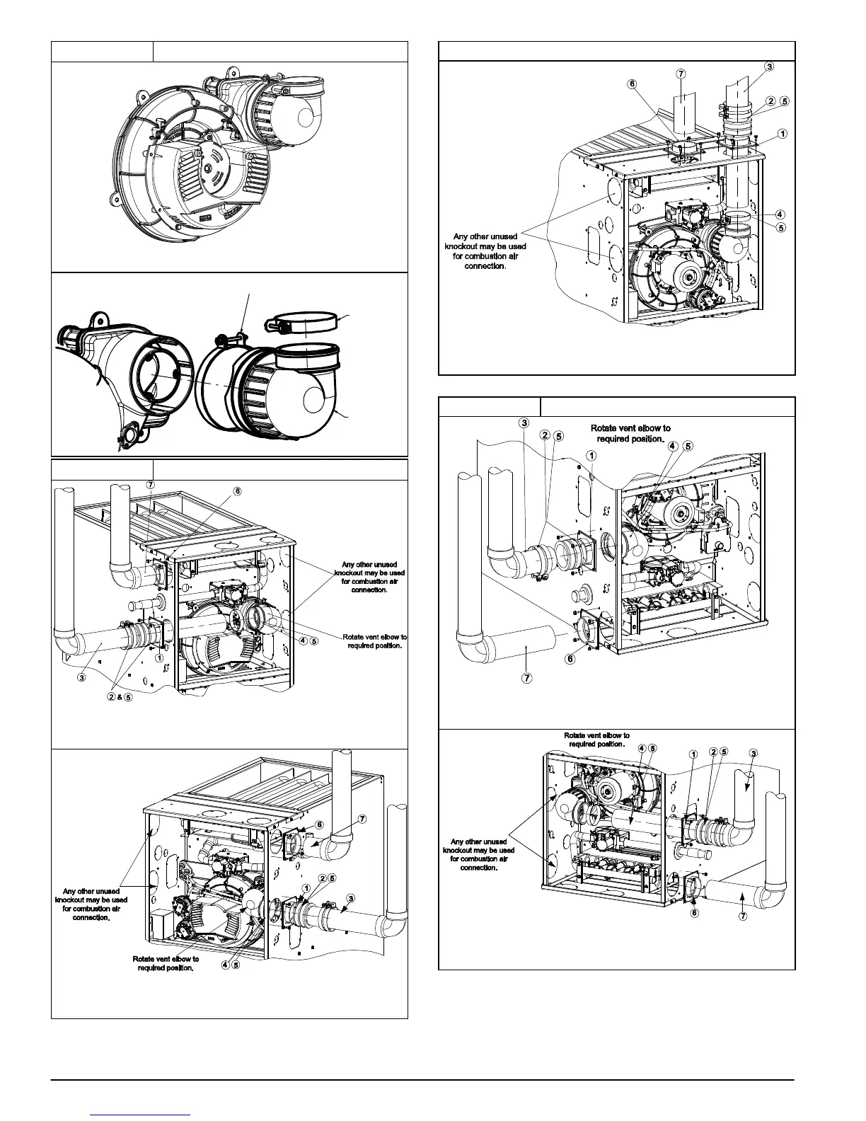
Figure 50 Inducer Vent Elbow − Variable
MODUL ATING INDUCER ASSEMBLY
INDUCER OUTLET
VENT ELBOW CL AMP
TORQUE 15 LB−IN.
VENT ELBOW
VENT PIPE CL AMP
TORQUE 15 LB−IN.
Figure 51 Upflow Configurations
A11309
Representative drawing only, some models may vary in appearance.
UPFLOW LEFT − VENT CONFIGURATION
A11308
Representative drawing only, some models may vary in appearance.
UPFLOW RIGHT − VENT CONFIGURATION
Upflow Configurations − continued
A11310
Representative drawing only, some models may vary in appearance.
UPFLOW VERTICAL − VENT CONFIGURATION
* See NOTES following figures.
Figure 52 Downflow Configurations
A11311
Representative drawing only, some models may vary in appearance.
DOWNFLOW LEFT − VENT CONFIGURATION
A11312
Representative drawing only, some models may vary in appearance.
DOWNFLOW RIGHT − VENT CONFIGURATION
* See NOTES following figures.