iDRY Series Heatless Regenerated Dryers: IOM10003-C (Rev. A) 15
7. CONTROLLER INFORMATION AND OPERATION
7.1 Display Overview
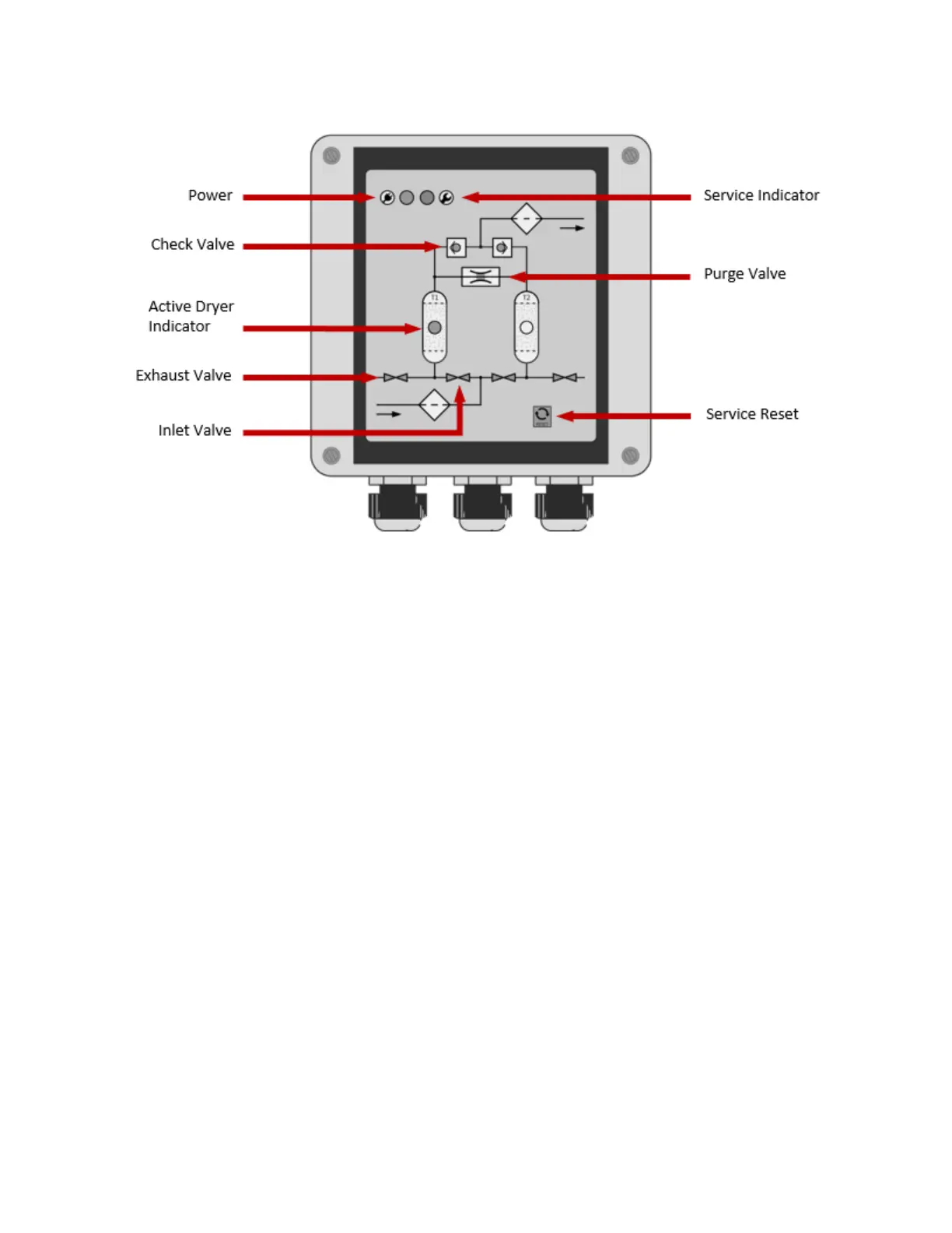
The LED illuminated PID controller interfaces between the dryer and the operator (shown above). The following pages
the detailed information about the controller’s settings and operation.
The controller has a total of nine LEDs to inform the operator its step in operation:
Two check valves indicating the direction of air flow out of the dryer
One purge valve indicator used during regeneration
Two LEDs are used to indicate the active dryer tower during operation
Four LEDs indicate purge exhaust valve and inlet valve PV- and IV-
The controller has two additional LEDs used to indicate power and service in the upper left corner of the display as shown
by the corresponding icons. During normal operation, the power LED is green and the service indicator LED is off.
7.2 Controller Startup
It is important to note that the controller is programed to run five times in succession for a short cycle. That is a 50%
shorter run times without consideration of the dew point input to bring the dryer to a defined state. After this startup
procedure the device is in normal operation mode.
During startup the compressor synchronization input is also active.
7.3 Controller Inputs
The controller and housing provide three M12 and two M16 glands on for its input / output connection lines. For input,
the connections are:
Power cable
Compressor-synchronization signal