iDRY Series Heatless Regenerated Dryers: IOM10003-C (Rev. A) 16
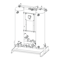
The input “compressor synchronization”, is meant to synchronize the
dryer with switching ON and OFF of the compressor. Hence, it
prevents a situation where the dryer continues to operate and use
rinsing air from the compressed air network though there is no supply
of compressed air. In case the voltage (120V AC-Input) drops at the
input, all valves are immediately closed.
After the compressor signal comes back online, the drying cycle is
continued from the same point, meaning that the last open valve also
opens again. Note two exceptions:
This is not valid if the remaining regeneration time is less than
30 seconds, in which case it immediately switches over to the
other drying column, which means the other valve is opened.
If the compressor is switched off for more than 24 hours, then
the device is started with five short full Nema cycles as though
the operating voltage has been interrupted (i.e. as after
RESET).
7.4 Controller Outputs
The controller outputs information two ways, one, to the controller
display, the other, to the dryer system through the housing glands:
Purge Exhaust Valve A
Purge Exhaust Valve B
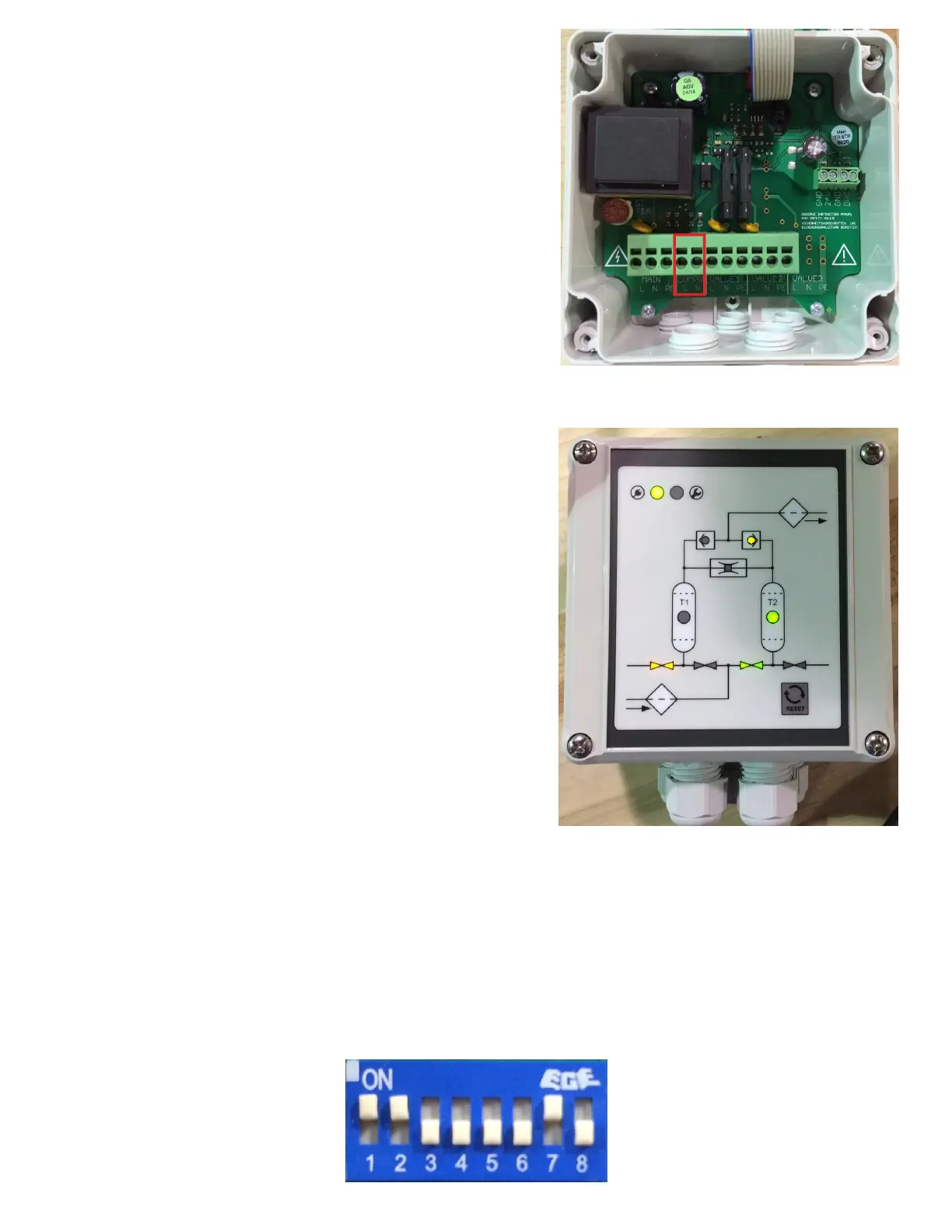
The controller outputs the dryer’s operational step to the controller
display LED indicators. This indicates the activated valves and drying
tower. In addition, the power light and service indicator are displayed.
The controller outputs an electrical signal to the tower selector
solenoid valve and energizes the appropriate valves based on dryer’s
step of operation.
7.5 Controller Settings
The controller unit has a total of eight DIP switches with the following parameters:
Three DIP switches are used to set the tower regeneration time
Two DIP switches are used to set the pressure build-up time
One DIP switch used for future expansion
One DIP switch aligns the controller with the compressor sync
One DIP switch used for future expansion
Below is a picture of the DIP switch control interface: