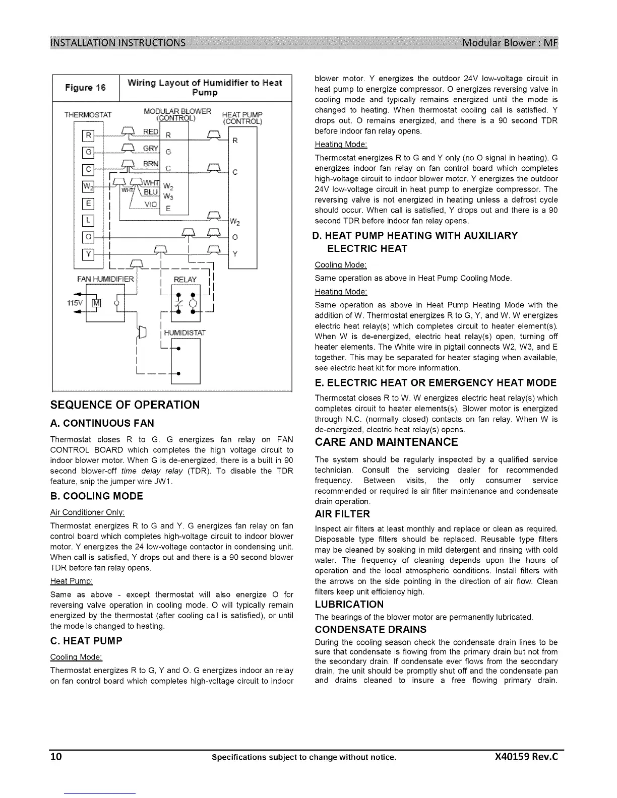
Figure 16 Wiring Layout of Humidifier to Heat
Pump
_DULAR BLOWER HEAT PUMP
(3ONTR_ L) (CONTROL}
F-_,_, _PR R
[] ............ _Ry G
r-q..... c ...............c
D I o
SEQUENCE OF OPERATION
A. CONTINUOUS FAN
Thermostat closes R to G. G energizes fan relay on FAN
CONTROL BOARD which completes the high voltage circuit to
indoor blower motor. When G is de-energized, there is a built in 90
second blower-off time delay relay (TDR). To disable the TDR
feature, snip the jumper wire JW1.
B. COOLING MODE
Air Conditioner Only:
Thermostat energizes R to G and Y. G energizes fan relay on fan
control board which completes high-voltage circuit to indoor blower
motor. Y energizes the 24 low-voltage contactor in condensing unit.
When call is satisfied, Y drops out and there is a 90 second blower
TDR before fan relay opens.
Heat Pump:
Same as above - except thermostat will also energize O for
reversing valve operation in cooling mode. O will typically remain
energized by the thermostat (after cooling call is satisfied), or until
the mode is changed to heating.
C. HEAT PUMP
Coolinq Mode:
Thermostat energizes R to G, Y and O. G energizes indoor an relay
on fan control board which completes high-voltage circuit to indoor
blower motor. Y energizes the outdoor 24V low-voltage circuit in
heat pump to energize compressor. O energizes reversing valve in
cooling mode and typically remains energized until the mode is
changed to heating. When thermostat cooling call is satisfied. Y
drops out. O remains energized, and there is a 90 second TDR
before indoor fan relay opens.
Heatinq Mode:
Thermostat energizes R to G and Y only (no O signal in heating). G
energizes indoor fan relay on fan control board which completes
high-voltage circuit to indoor blower motor. Y energizes the outdoor
24V low-voltage circuit in heat pump to energize compressor. The
reversing valve is not energized in heating unless a defrost cycle
should occur. When call is satisfied, Y drops out and there is a 90
second TDR before indoor fan relay opens.
D. HEAT PUMP HEATING WITH AUXILIARY
ELECTRIC HEAT
Coolinq Mode:
Same operation as above in Heat Pump Cooling Mode.
Heatinq Mode:
Same operation as above in Heat Pump Heating Mode with the
addition of W. Thermostat energizes R to G, Y, and W. W energizes
electric heat relay(s) which completes circuit to heater element(s).
When W is de-energized, electric heat relay(s) open, turning off
heater elements. The White wire in pigtail connects W2, W3, and E
together. This may be separated for heater staging when available,
see electric heat kit for more information.
E. ELECTRIC HEAT OR EMERGENCY HEAT MODE
Thermostat closes R to W. W energizes electric heat relay(s) which
completes circuit to heater elements(s). Blower motor is energized
through N.C. (normally closed) contacts on fan relay. When W is
de-energized, electric heat relay(s) opens.
CARE AND MAINTENANCE
The system should be regularly inspected by a qualified service
technician. Consult the servicing dealer for recommended
frequency. Between visits, the only consumer service
recommended or required is air filter maintenance and condensate
drain operation.
AIR FILTER
Inspect air filters at least monthly and replace or clean as required.
Disposable type filters should be replaced. Reusable type filters
may be cleaned by soaking in mild detergent and rinsing with cold
water. The frequency of cleaning depends upon the hours of
operation and the local atmospheric conditions. Install filters with
the arrows on the side pointing in the direction of air flow. Clean
filters keep unit efficiency high.
LUBRICATION
The bearings of the blower motor are permanently lubricated.
CONDENSATE DRAINS
During the cooling season check the condensate drain lines to be
sure that condensate is flowing from the primary drain but not from
the secondary drain. If condensate ever flows from the secondary
drain, the unit should be promptly shut off and the condensate pan
and drains cleaned to insure a free flowing primary drain.
10 Specifications subject to change without notice. X40159 Rev.C
 Loading...