iiiiiiiiiiiiiiiiil_!i!i!i!i!_i!_!i!i!i!iii;l!:;!%!i_iliiiiiiiiiiiiiiiiiiiiiliiiiiiiiil_iiiiiiiiiiili%iiiiiiiiiiiilii
i!i!i!i!i!i!i!i!i!i!i!iiii ii ii i! i ii ii i ii ii i! i ii ii ii ii ii ii ii ii ii ii ii iiiiiiiiiiiiiiiiiiiiili
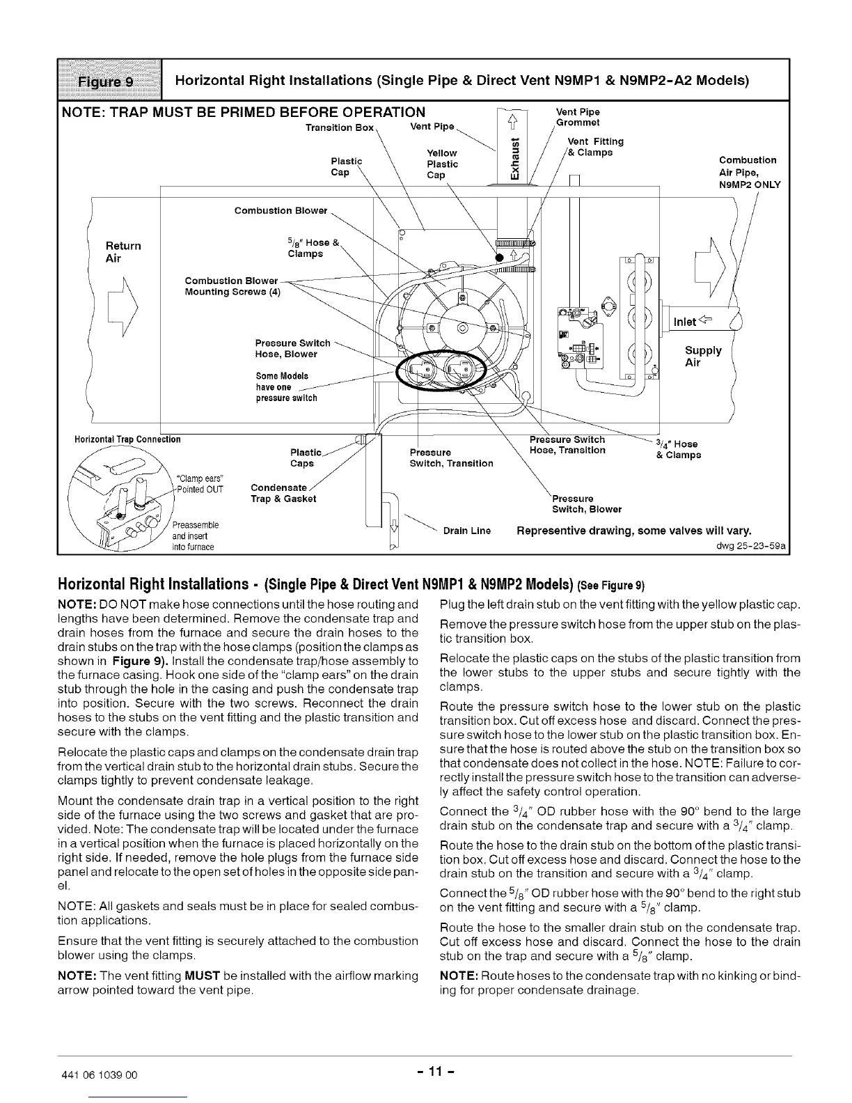
NOTE: TRAP MUST BE PRIMED BEFORE OPERATION
Transition Box
Horizontal Right Installations (Single Pipe & Direct Vent N9MP1 & N9MP2-A2 Models)
Vent Pipe
Grommet
Vent Fitting
Plastic Combustion
Cap Air Pipe,
NBMP2 ONLY
Return
Air
Combustion Blower
5/8"
Clamps
Combustion Blower-
Mounting Screws (4)
Pressure Switch
Hose, Blower
SomeModels
haveone
pressureswitch
E
_ Inlet<3=
Supply
Air
Horizontal TrapConnection
"Clampears"
PointedOUT
'reassemble
andinsert
into furnace
Plastic
Caps
Condensate
Trap & Gasket
Pressure
Switch, Transition
Drain Line
3/4" Hose
Hose, Transition & Clamps
Switch, Blower
Rspresentivs drawing, some valves will vary.
dwg 25-23-59a
Horizontal Right Installations - (Single Pipe &Direct Vent NBMP1 & N9MP2 Models) (SeeFigure9)
NOTE: DO NOT make hose connections until the hose routing and
lengths have been determined. Remove the condensate trap and
drain hoses from the furnace and secure the drain hoses to the
drain stubs on the trap with the hose clamps (position the clamps as
shown in Figure 9). Install the condensate trap/hose assembly to
the furnace casing. Hook one side of the "clamp ears" on the drain
stub through the hole in the casing and push the condensate trap
into position. Secure with the two screws. Reconnect the drain
hoses to the stubs on the vent fitting and the plastic transition and
secure with the clamps.
Relocate the plastic caps and clamps on the condensate drain trap
from the vertical drain stub to the horizontal drain stubs. Secure the
clamps tightly to prevent condensate leakage.
Mount the condensate drain trap in a vertical position to the right
side of the furnace using the two screws and gasket that are pro-
vided. Note: The condensate trap will be located under the furnace
in a vertical position when the furnace is placed horizontally on the
right side. If needed, remove the hole plugs from the furnace side
panel and relocate to the open set of holes in the opposite side pan-
el.
NOTE: All gaskets and seals must be in place for sealed combus-
tion applications.
Ensure that the vent fitting is securely attached to the combustion
blower using the clamps.
NOTE: The vent fitting MUST be installed with the airflow marking
arrow pointed toward the vent pipe.
Plug the left drain stub on the vent fitting with the yellow plastic cap.
Remove the pressure switch hose from the upper stub on the plas-
tic transition box.
Relocate the plastic caps on the stubs of the plastic transition from
the lower stubs to the upper stubs and secure tightly with the
clamps.
Route the pressure switch hose to the lower stub on the plastic
transition box. Cut off excess hose and discard. Connect the pres-
sure switch hose to the lower stub on the plastic transition box. En-
sure that the hose is routed above the stub on the transition box so
that condensate does not collect in the hose. NOTE: Failure to cor-
rectly install the pressure switch hose to the transition can adverse-
ly affect the safety control operation.
Connect the 3/4" OD rubber hose with the 90 ° bend to the large
drain stub on the condensate trap and secure with a 3/4" clamp.
Route the hose to the drain stub on the bottom ofthe plastic transi-
tion box. Cut off excess hose and discard. Connect the hose to the
drain stub on the transition and secure with a 3/4" clamp.
Connect the 5/8" OD rubber hose with the 90 ° bend to the right stub
on the vent fitting and secure with a 5/8" clamp.
Route the hose to the smaller drain stub on the condensate trap.
Cut off excess hose and discard. Connect the hose to the drain
stub on the trap and secure with a 5/8" clamp.
NOTE: Route hoses to the condensate trap with no kinking or bind-
ing for proper condensate drainage.
441 06 1039 00 - 11 -
 Loading...

