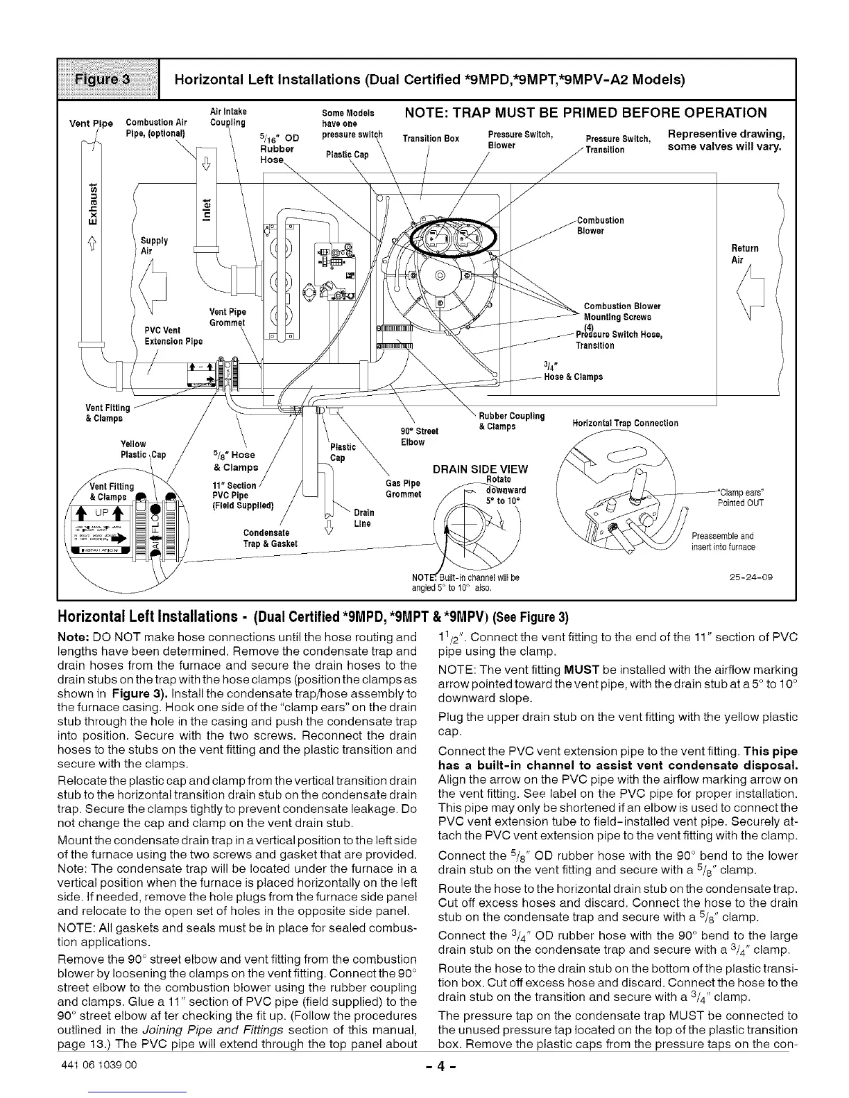
Horizontal Left Installations (Dual Certified *9MPD,*9MPT,*9MPV-A2 Models)
Airlntake $omeModete NOTE: TRAP MUST BE PRIMED BEFORE OPERATION
Coul have one
5/16" OD TransitionBox PressureSwitch, PressureSwitch, Representive drawing,
Rubber Blower somevalves will vary.
ipe
CombustionAir
Pipe,(optional)
Supply
Air
PVCVent
ExtensionPipe
VentPipe
Blower
CombustionBlower
g Screws
Rose,
Transition
Return
Air
Vent Fitting
&Clamps
Yellow
Plastic 5/8" Hose
RubberCoupling
90° Street & Clamps
Elbow
DRAIN SIDEVIEW
• Rotate
Gas Pipe
Grommet f [,<7- do_ward
NOTE_.Built-in channelwill be
angled5° to 10° also.
HorizontalTrapConnection
Ipears"
PointedOUT
Preassembleand
insertintofurnace
25-24-09
Horizontal Left Installations - (Dual Certified*9MPD, *9MPT &*9MPV) (SeeFigure3)
Note: DO NOT make hose connections until the hose routing and
lengths have been determined, Remove the condensate trap and
drain hoses from the furnace and secure the drain hoses to the
drain stubs on the trap with the hose clamps (position the clamps as
shown in Figure 3). Install the condensate trap/hose assembly to
the furnace casing, Hook one side of the "clamp ears" on the drain
stub through the hole in the casing and push the condensate trap
into position. Secure with the two screws. Reconnect the drain
hoses to the stubs on the vent fitting and the plastic transition and
secure with the clamps.
Relocate the plastic cap and clamp from the vertical transition drain
stub to the horizontal transition drain stub on the condensate drain
trap. Secure the clamps tightly to prevent condensate leakage. Do
not change the cap and clamp on the vent drain stub.
Mount the condensate drain trap in a vertical position to the left side
of the furnace using the two screws and gasket that are provided.
Note: The condensate trap will be located under the furnace in a
vertical position when the furnace is placed horizontally on the left
side. If needed, remove the hole plugs from the furnace side panel
and relocate to the open set of holes in the opposite side panel.
NOTE: All gaskets and seals must be in place for sealed combus-
tion applications.
Remove the 90 ° street elbow and vent fitting from the combustion
blower by loosening the clamps on the vent fitting. Connect the 90 °
street elbow to the combustion blower using the rubber coupling
and clamps. Glue a 11" section of PVC pipe (field supplied) to the
90 ° street elbow after checking the fit up. (Follow the procedures
outlined in the Joining Pipe and Fittings section of this manual,
page 13.) The PVC pipe will extend through the top panel about
11/2"• Connect the vent fitting to the end of the 11" section of PVC
pipe using the clamp.
NOTE: The vent fitting MUST be installed with the airflow marking
arrow pointed toward the vent pipe, with the drain stub at a 5° to 10°
downward slope.
Plug the upper drain stub on the vent fitting with the yellow plastic
cap.
Connect the PVC vent extension pipe to the vent fitting. This pipe
has a built-in channel to assist vent condensate disposal.
Align the arrow on the PVC pipe with the airflow marking arrow on
the vent fitting• See label on the PVC pipe for proper installation,
This pipe may only be shortened if an elbow is used to connect the
PVC vent extension tube to field-installed vent pipe, Securely at-
tach the PVC vent extension pipe to the vent fitting with the clamp.
Connect the 5/8" OD rubber hose with the 90° bend to the lower
drain stub on the vent fitting and secure with a 5/8" clamp.
Route the hose to the horizontal drain stub on the condensate trap.
Cut off excess hoses and discard. Connect the hose to the drain
stub on the condensate trap and secure with a 5/8" clamp.
Connect the 3/4" OD rubber hose with the 90° bend to the large
drain stub on the condensate trap and secure with a 3/4" clamp.
Route the hose to the drain stub on the bottom ofthe plastic transi-
tion box• Cut off excess hose and discard. Connect the hose to the
drain stub on the transition and secure with a 3/4" clamp.
The pressure tap on the condensate trap MUST be connected to
the unused pressure tap located on the top of the plastic transition
box• Remove the plastic caps from the pressure taps on the con-
441 06 1039 00 - 4 -