densatetrapandtheplastictransitionandconnectwiththe5/16"
ODrubberhose.
NOTE:Thiswillrequiredrillinga5/16"ODholeinthefurnacecasing
nexttothecondensatetrap.
NOTE:Ensurehosesmaintainadownwardslopetotheconden-
satetrapwithnokinkingorbindingforpropercondensatedrain-
age.
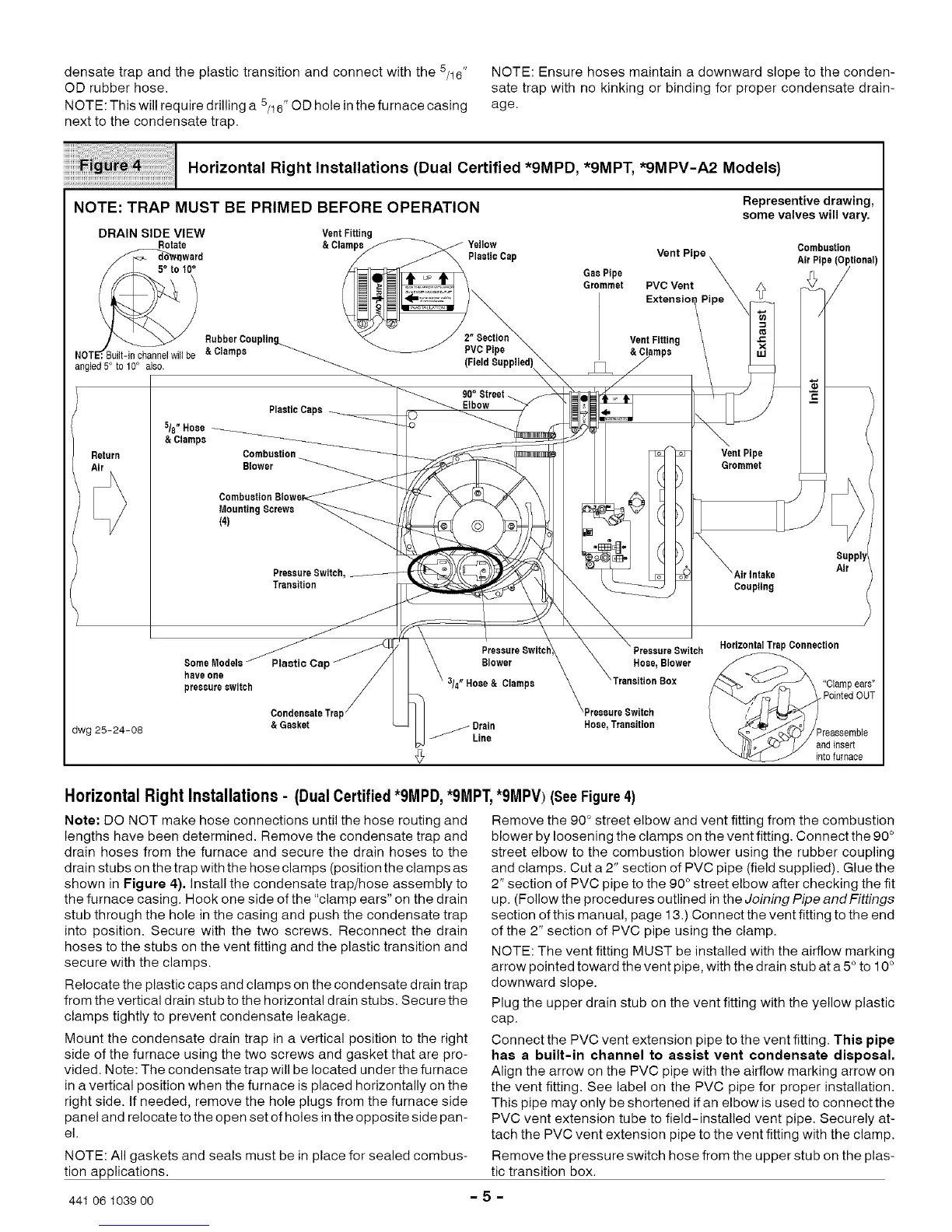
Horizontal Right Installations (Dual Certified *9MPD, *9MPT, *9MPV-A2 Models)
NOTE: TRAP MUST BE PRIMED BEFORE OPERATION
DRAIN SIDE VIEW VentFitting
Rotate &Clampe_ Yellow
_ward f _ _ PlaaticCap
j _ RubberCoupling._ _ /" 2[.Secyion
NOTE_':Built-inchannelwillbe &Clamps _ _ PVCPipe ..
angled 5° to10° als0. _ (Field Bupplied)\_
Return
dwg 25-24-08
Representive drawing,
some valves will vary.
GasPipe
Grommet
Vent PipeX
PVCVent _ _¢
Extenoi°n/PiPe _i
V&e;tFmit;isng \ x
Combustion
AirPipe(Optional)
/
/
90° Street-__ _ _ c
5/8"Hose _ PlasticCaps_ -1_ _
&Clamps __ _
Combustion _ qo _' _ VentPipe
Blower _i_c ,___ _ G_ommet I_/_
CombustionBlowek_ _ E
MountingScrews _ O _ )
(4)
_ _ / Supply
PreaeureSwitch,__ )_'\__o__ Airlntake Air
Transition _<_ __ Coupling
!ieV_20_ide_t_C_e_ill ' \\ BIowerPressureSwitch_,,_ \Preeeare_X Hose,BIowerSWitch/_> _J\_H°riz°ntalTrapConnection
3/4"Hose& Clamps --Transition Box ,,pOplart Pde_rus,T
r i / _'_/_
\ II_lo_o" _1 aodinsert
_ int0furnace
Horizontal Right Installations - (Dual Certified *9MPD, *9MPT,*9MPV) (SeeFigure4)
Note: DO NOT make hose connections until the hose routing and
lengths have been determined. Remove the condensate trap and
drain hoses from the furnace and secure the drain hoses to the
drain stubs on the trap with the hose clamps (position the clamps as
shown in Figure 4). Install the condensate trap/hose assembly to
the furnace casing. Hook one side of the "clamp ears" on the drain
stub through the hole in the casing and push the condensate trap
into position. Secure with the two screws. Reconnect the drain
hoses to the stubs on the vent fitting and the plastic transition and
secure with the clamps.
Relocate the plastic caps and clamps on the condensate drain trap
from the vertical drain stub to the horizontal drain stubs. Secure the
clamps tightly to prevent condensate leakage.
Mount the condensate drain trap in a vertical position to the right
side of the furnace using the two screws and gasket that are pro-
vided. Note: The condensate trap will be located under the furnace
in a vertical position when the furnace is placed horizontally on the
right side. If needed, remove the hole plugs from the furnace side
panel and relocate to the open set of holes in the opposite side pan-
el.
NOTE: All gaskets and seals must be in place for sealed combus-
tion applications.
Remove the 90 ° street elbow and vent fitting from the combustion
blower by loosening the clamps on the vent fitting. Connect the 90 °
street elbow to the combustion blower using the rubber coupling
and clamps. Cut a 2" section of PVC pipe (field supplied). Glue the
2" section of PVC pipe to the 90 ° street elbow after checking the fit
up. (Follow the procedures outlined in the Joining Pipe and Fittings
section of this manual, page 13.) Connect the vent fitting to the end
of the 2" section of PVC pipe using the clamp.
NOTE: The vent fitting MUST be installed with the airflow marking
arrow pointed toward the vent pipe, with the drain stub at a 5 ° to 10 °
downward slope.
Plug the upper drain stub on the vent fitting with the yellow plastic
cap.
Connect the PVC vent extension pipe to the vent fitting. This pipe
has a built-in channel to assist vent condensate disposal.
Align the arrow on the PVC pipe with the airflow marking arrow on
the vent fitting. See label on the PVC pipe for proper installation.
This pipe may only be shortened if an elbow is used to connect the
PVC vent extension tube to field-installed vent pipe. Securely at-
tach the PVC vent extension pipe to the vent fitting with the clamp.
Remove the pressure switch hose from the upper stub on the plas-
tic transition box.
441 06 1039 oo - 5 -