iiiiiiiiiiiiiiiiil;i!¸I!I¸!i¸i!!i;i¸iiiilil¸¸lllii_lllllll!_!iiiiiillll!l!l!l!l!llllll_l_l_l_l_l_l_l_l_l_l_l_l_l_l_l_l_l_l_l_l_l_!
NOTE: TRAP MUST BE PRIMED BEFORE OPERATION
DRAIN SIDEVIEW 0 I
VentFitting SupplyAir
!B &Clamps PVCVent
ExtensionPipe
: • _. •NOT u_lt_nchannelw_ll
beangled5°to 10° also. VentPi
LEFT Side Venting
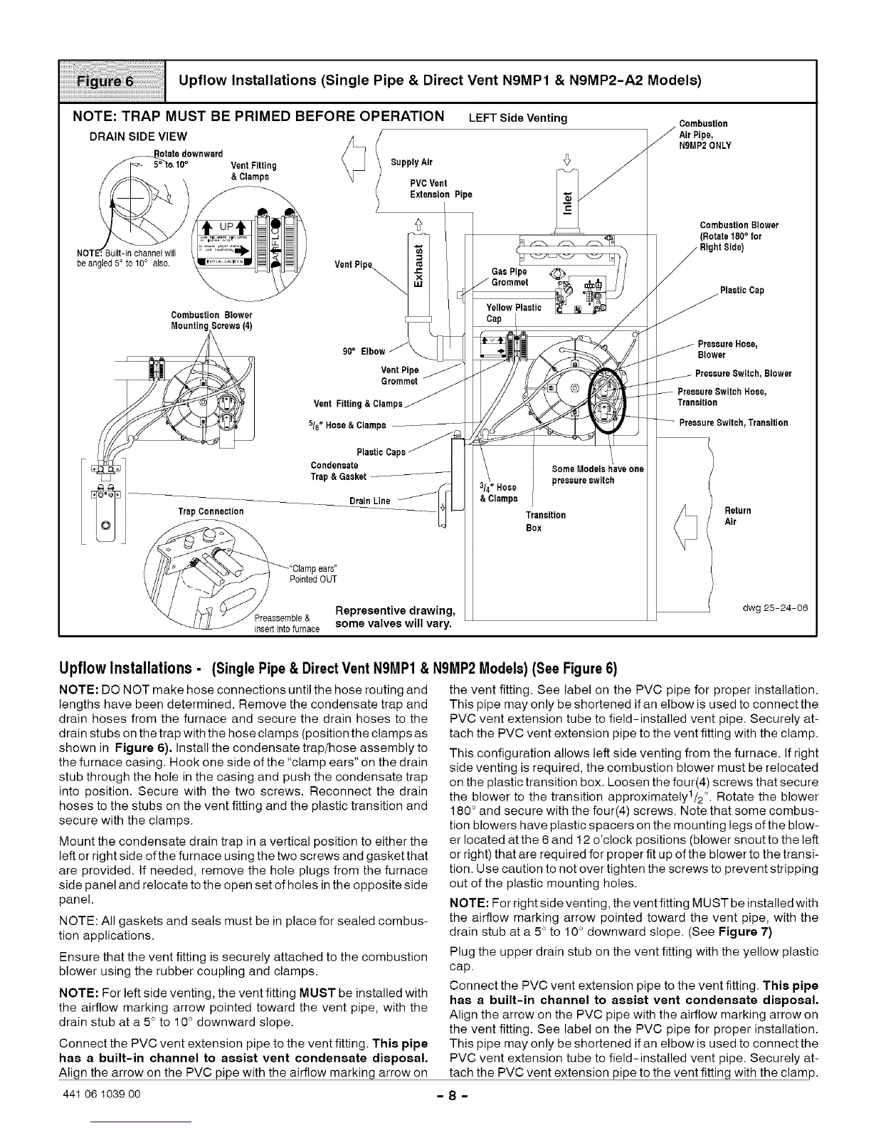
Upflow Installations (Single Pipe & Direct Vent N9MP1 & N9MP2-A2 Models)
CombasUon
N9MP2ONLY
Combaetion Blower
(Rotate 180° for
RightSide)
PlasticCap
Combustion Blower
MountingScrews(4)
90= VentPipe
Grommet
VentFitting&Clamps
5/8"Hose&Clamps
Condensate
Trap& Gasket
DrainLine
TrapConnection
"Ctampears"
_/ PointedOUT
/ Representive drawing,
J Preaeeemble& some valves will vary.
insertintofurnace
& Clamps
SomeModelshave one
pressureswitch
Transition
Box
PressureHose,
Blower
I, Blower
PressureSwitchHose,
Transition
PressureSwitch,Transition
Return
Air
dwg 25-24-06
Upflow Installations - (Single Pipe & Direct Vent N9MP1 &
NOTE: DO NOT make hose connections until the hose routing and
lengths have been determined. Remove the condensate trap and
drain hoses from the furnace and secure the drain hoses to the
drain stubs on the trap with the hose clamps (position the clamps as
shown in Figure 6). Install the condensate trap/hose assembly to
the furnace casing. Hook one side of the "clamp ears" on the drain
stub through the hole in the casing and push the condensate trap
into position. Secure with the two screws. Reconnect the drain
hoses to the stubs on the vent fitting and the plastic transition and
secure with the clamps.
Mount the condensate drain trap in a vertical position to either the
left or right side of the furnace using the two screws and gasket that
are provided. If needed, remove the hole plugs from the furnace
side panel and relocate to the open set of holes in the opposite side
panel.
NOTE: All gaskets and seals must be in place for sealed combus-
tion applications.
Ensure that the vent fitting is securely attached to the combustion
blower using the rubber coupling and clamps.
NOTE: For left side venting, the vent fitting MUST be installed with
the airflow marking arrow pointed toward the vent pipe, with the
drain stub at a 5° to 10 ° downward slope.
Connect the PVC vent extension pipe to the vent fitting. This pipe
has a built-in channel to assist vent condensate disposal.
Align the arrow on the PVC pipe with the airflow marking arrow on
N9MP2 Models) (See Figure 6)
the vent fitting. See label on the PVC pipe for proper installation.
This pipe may only be shortened if an elbow is used to connect the
PVC vent extension tube to field-installed vent pipe. Securely at-
tach the PVC vent extension pipe to the vent fitting with the clamp.
This configuration allows left side venting from the furnace. If right
side venting is required, the combustion blower must be relocated
on the plastic transition box. Loosen the four(4) screws that secure
the blower to the transition approximately1/2 ". Rotate the blower
180 ° and secure with the four(4) screws. Note that some combus-
tion blowers have plastic spacers on the mounting legs of the blow-
er located atthe 6 and 12 o'clock positions (blower snout to the left
or right) that are required for proper fit up of the blower to the transi-
tion. Use caution to not over tighten the screws to prevent stripping
out of the plastic mounting holes.
NOTE: For right side venting, the vent fitting MUST be installed with
the airflow marking arrow pointed toward the vent pipe, with the
drain stub at a 5 ° to 10 ° downward slope. (See Figure 7)
Plug the upper drain stub on the vent fitting with the yellow plastic
cap.
Connect the PVC vent extension pipe to the vent fitting. This pipe
has a built-in channel to assist vent condensate disposal.
Align the arrow on the PVC pipe with the airflow marking arrow on
the vent fitting. See label on the PVC pipe for proper installation.
This pipe may only be shortened if an elbow is used to connect the
PVC vent extension tube to field-installed vent pipe. Securely at-
tach the PVC vent extension pipe to the vent fitting with the clamp.
441 06 1039 00 - 8 -