Plugtheupperdrainstubontheventfittingwiththeyellowplastic
cap.
ConnectthePVCventextensionpipetotheventfitting.Thispipe
has a built-in channel to assist vent condensate disposal.
Align the arrow on the PVC pipe with the airflow marking arrow on
the vent fitting. See label on the PVC pipe for proper installation.
This pipe may only be shortened if an elbow is used to connect the
PVC vent extension tube to field-installed vent pipe. Securely at-
tach the PVC vent extension pipe to the vent fitting with the clamp.
Remove the pressure switch hose from the upper stub on the plas-
tic transition box.
Relocate the plastic caps on the stubs of the plastic transition box
from the lower stubs to the upper stubs and secure tightly with the
clamps.
Route the pressure switch hose to the lower stub on the plastic
transition box. Cut off excess hose and discard. Connect the pres-
sure switch hose to the lower stub on the plastic transition box.
NOTE: Failure to correctly install the pressure switch hose to the
transition box can adversely affect the safety control operation.
Connect the 3/4" OD rubber hose with the 90 ° bend to the drain stub
on the bottom of the plastic transition box and secure with a 3/4"
clamp.
Route the hose to the large drain stub on the condensate trap. Cut
off excess hose and discard. Connect the hose to the drain stub on
the transition and secure with a 3/4" clamp.
Connect the 5/8" OD rubber hose with the 90 ° bend to the left drain
stub on the vent fitting and secure with a 5/8" clamp.
Route the hose to the smaller stub on the condensate trap. Cut off
excess hose and discard. Connect the hose to the drain stub on the
trap and secure with a 5/8" clamp.
Note: The air intake coupling and gasket can be installed to the top
panel to the alternate air intake locations on either the left or right
side panels of the furnace.
For downflow installation, the air intake coupling and gasket must
be installed to the alternate air intake location on either the left or
right side panels. Remove the 3" hole plug from the side panel and
relocate to the air intake hole in the top panel. Use four screws to
seal the four(4) mounting holes in the top panel next to the hole
plug. Drill four(4) 7/64" diameter holes in the casing using the air in-
take coupling as the template.
The air intake coupling is sized for 2" PVC pipe.
Install the combustion air pipe to the air intake coupling using RTV
sealant to provide for future serviceability.
Vent Pipe Connection
Install the vent pipe grommet to the furnace panel. Locate the
grommet in the furnace panel at a location directly away from the
vent fitting on the combustion blower. The grommet snaps into the
3" hole plug from the furnace panel. NOTE: Depending on the
installation position, the vent pipe grommet will be installed to the
top panel or to the alternate location on the side panels. If needed,
remove the 3" hole plug from the furnace panel and relocate to the
open hole in the furnace panel, (See Figure 5 or Figure 10)
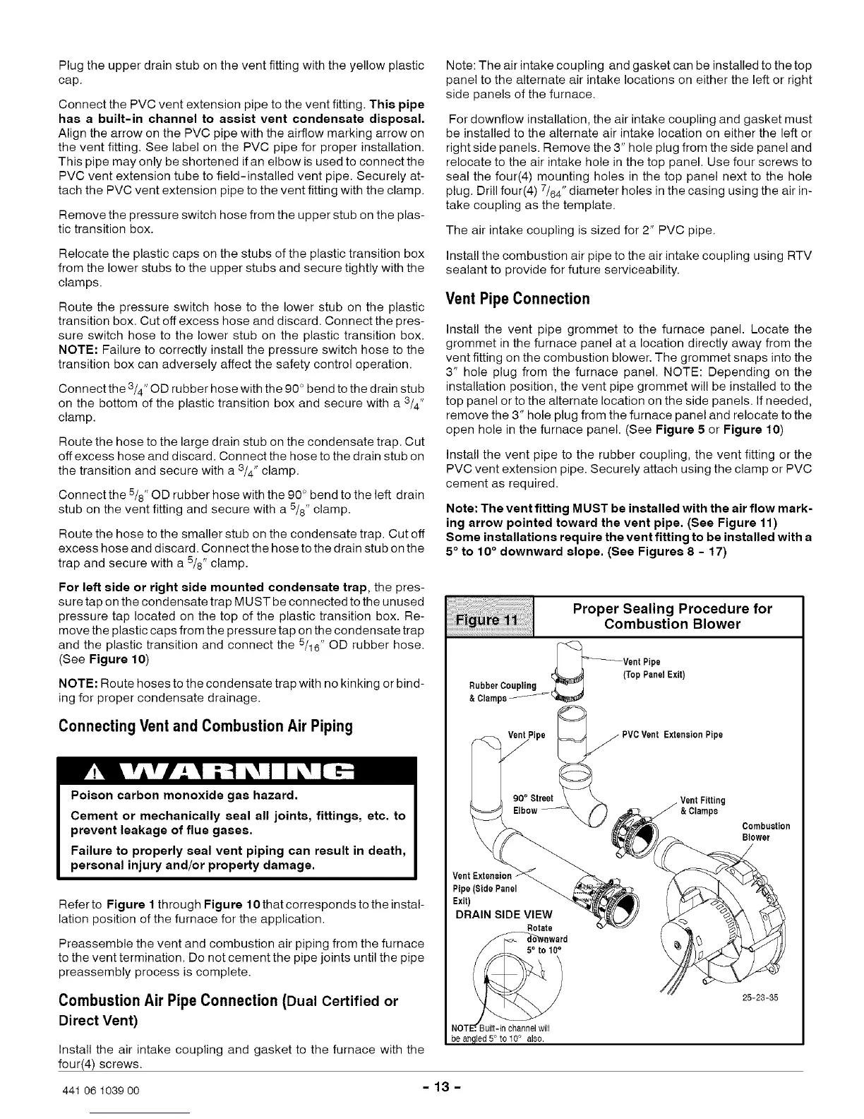
Install the vent pipe to the rubber coupling, the vent fitting or the
PVC vent extension pipe. Securely attach using the clamp or PVC
cement as required.
Note: The vent fitting MUST be installed with the air flow mark-
ing arrow pointed toward the vent pipe. (See Figure 11)
Some installations require the vent fitting to be installed with a
5 ° to 10° downward slope. (See Figures 8 - 17)
For left aide or right aide mounted condenaate trap, the pres-
sure tap on the condensate trap MUST be connected to the unused
pressure tap located on the top of the plastic transition box. Re-
move the plastic caps from the pressure tap on the condensate trap
and the plastic transition and connect the 5/16" OD rubber hose.
(See Figure 10)
NOTE: Route hoses to the condensate trap with no kinking or bind-
ing for proper condensate drainage.
ConnectingVent and Combustion Air Piping
Poison carbon monoxide gas hazard.
Cement or mechanically seal all joints, fittings, etc. to
prevent leakage of flue gases.
Failure to properly seal vent piping can result in death,
personal injury and/or property damage.
Refer to Figure 1 through Figure 10 that corresponds to the instal-
lation position of the furnace for the application,
Preassemble the vent and combustion air piping from the furnace
to the vent termination. Do not cement the pipe joints until the pipe
preassembly process is complete.
Combustion Air Pipe Connection (Dual Certified or
Direct Vent)
Install the air intake coupling and gasket to the furnace with the
four(4) screws.
RubbaerpC°upting _
90° Streetl
Elbow
Pipe(SidePanel
Exit)
DRAIN SIDE VIEW
Rotate
//_6v_ward
NOTE',Built-inchannelwill
beanqled5°to 10° als0.
Proper Sealing Procedure for
Combustion Blower
_Vent Pipe
(Top PanelExit)
_PVC VentExtensionPipe
/ VentFitting
&Clamps
Combustion
Blower
/
)
25-23-35
441 06 1039 00 - 13 -
 Loading...

