iiiiiiiiiiiiiiiiil;i!¸I!I¸!i¸i!!gilililil¸¸ll_ggilll!_!iiiiiillll!l!l!l!l!l!gl_l_l_l_l_l_l_l_l_l_l_l_l_l_l_l_l_l_l_l_l_l_!
DRAIN SIDE VIEW
Rotate
5° to 10°
angled5° to 10° also.
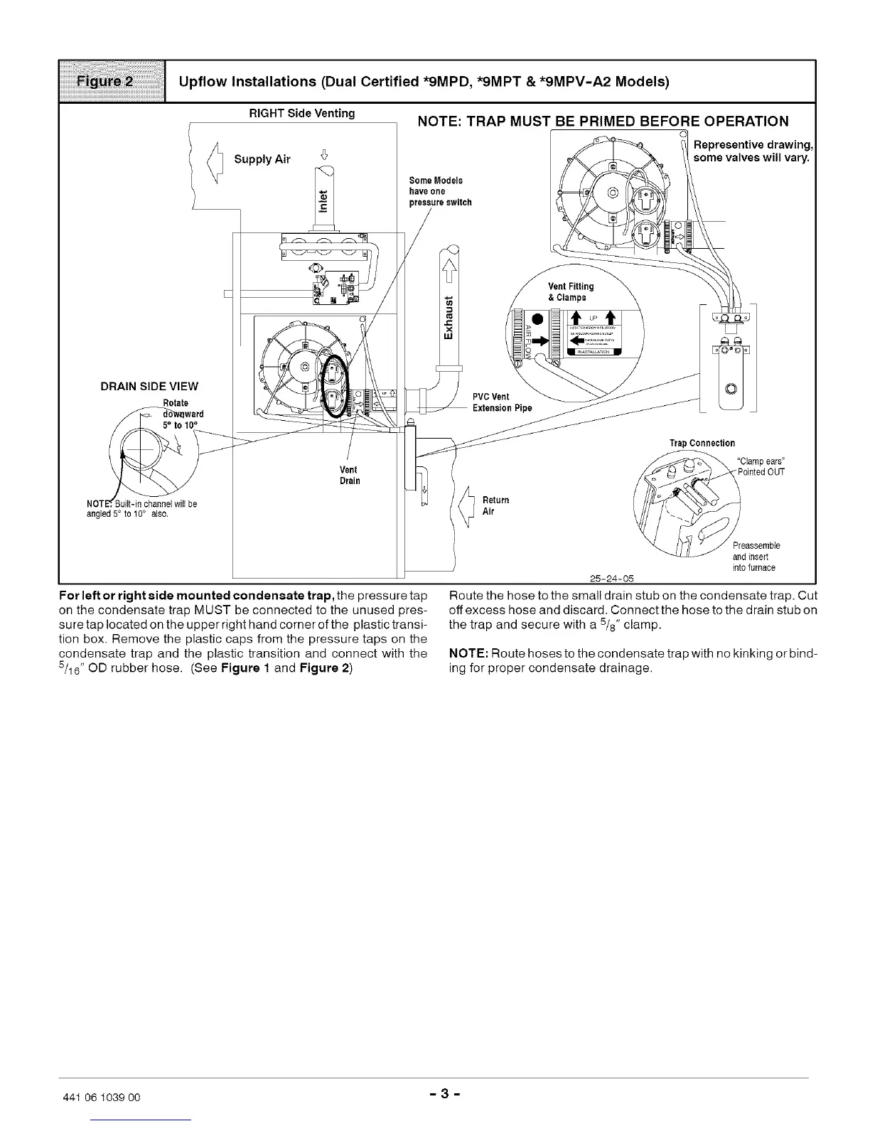
Upflow Installations (Dual Certified *9MPD, *9MPT & *9MPV-A2 Models)
RIGHT Side Venting
Supply Air
0
Vent
Drain
For left or right side mounted condensate trap, the pressure tap
on the condensate trap MUST be connected to the unused pres-
sure tap located on the upper right hand corner of the plastic transi-
tion box. Remove the plastic caps from the pressure taps on the
condensate trap and the plastic transition and connect with the
5/16" OD rubber hose. (See Figure 1 and Figure 2)
NOTE: TRAP MUST BE PRIMED BEFORE OPERATION
Some Models
have one
Representive drawing,
some valves will vary.
Vent Fitting
&Clamps
PVCVent
ExtensionPipe
TrapConnection
'_Clampears"
_PointedOUT
Return
Air
Preassemble
andinsert
int0furnace
25-24-05
Route the hose to the small drain stub on the condensate trap. Cut
off excess hose and discard, Connect the hose to the drain stub on
the trap and secure with a 5/8" clamp.
NOTE: Route hoses to the condensate trap with no kinking or bind-
ing for proper condensate drainage.
441 06 1039 O0 - 3 -