Relocatetheplasticcapsonthestubsoftheplastictransitionbox
fromthelowerstubstotheupperstubsandsecuretightlywiththe
clamps.
Routethepressureswitchhosetothelowerstubontheplastic
transitionbox.Cutoffexcesshoseanddiscard.Connectthepres-
sureswitchhosetothelowerstubontheplastictransitionbox.En-
surethatthehoseisroutedabovethestubonthetransitionboxso
thatcondensatedoesnotcollectinthehose.NOTE:Failuretocor-
rectlyinstallthepressureswitchhosetothetransitioncanadverse-
lyaffectthesafetycontroloperation.
Connectthe3/4"ODrubberhosewiththe90° bendtothelarge
drainstubonthecondensatetrapandsecurewitha3/4"clamp.
Routethehosetothedrainstubonthebottomoftheplastictransi-
tionbox.Cutoffexcesshoseanddiscard.Connectthehosetothe
drainstubonthetransitionandsecurewitha3/4"clamp.
Connectthe5/8"ODrubberhosewiththe90°bendtothelower
drainstubontheventfittingandsecurewitha5/8"clamp.
Routethehosetothesmallerdrainstubonthecondensatetrap.
Cutoffexcesshoseanddiscard.Connectthehosetothedrain
stubonthetrapandsecurewitha5/8"clamp.
NOTE:Routehosestothecondensatetrapwithnokinkingorbind-
ingforpropercondensatedrainage.
iiiiiiiiiiiiiiiii¸iiiiiiiiiiiiiiii_ii;iiiiiiiiiii¸i¸i¸i¸i¸i¸i¸i!il¸i¸i¸iiiiiiiiiii!!iiiiiiiiiiiiiiiiiiiiiiiiiiii!!i
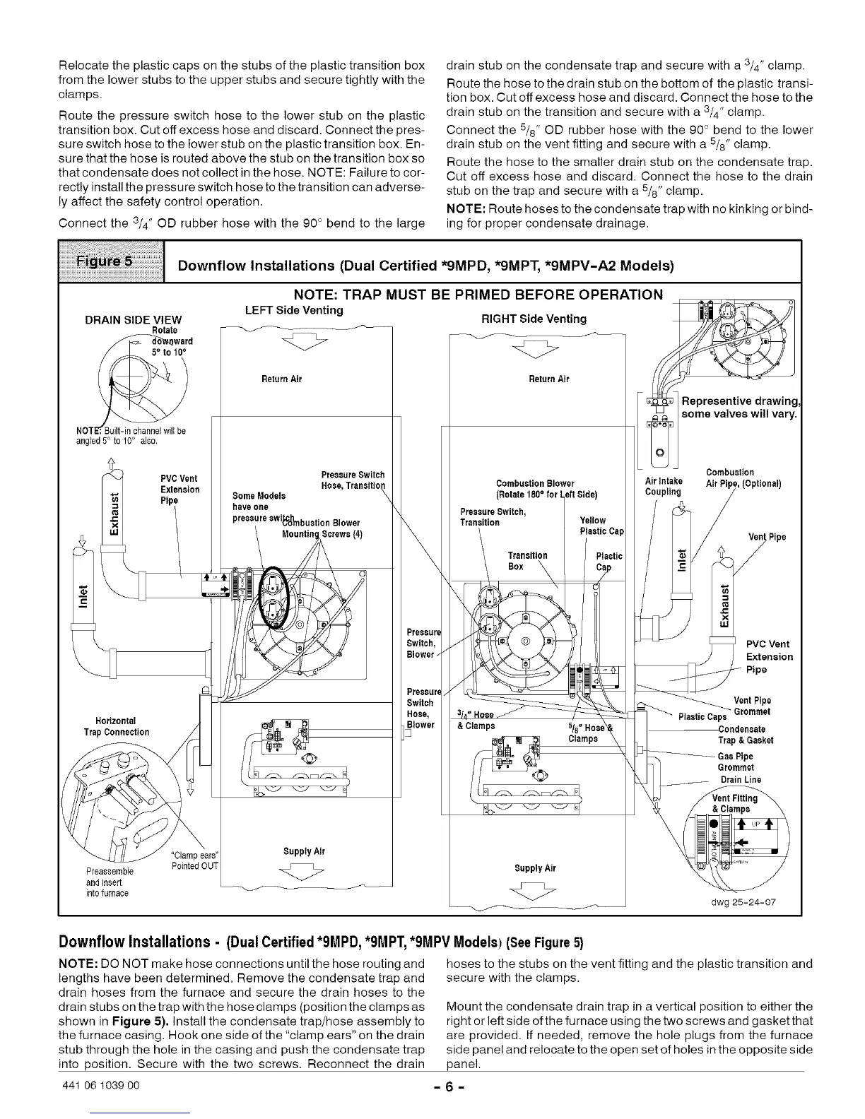
NOTE: TRAP MUST BE PRIMED BEFORE OPERATION
DRAIN SIDE VIEW
Rotate
5° to t0 °
_uilt-in channel will be
angled5 ° to 10° als0.
Horizontal
Trap Connection
PVCVent
Extension
Pipe
LEFT Side Venting
<Z>
ReturnAir
PressureSwitch
Some Models Hose,Traneitio_--
haveone
pressureowi_nbaotion Blower
Screws (4)
SupplyAir
<Z>
Preoaar_
Switch,
Blower-
Preoear(
Switch
Hose,
RIGHT Side Venting
<Z>
ReturnAir
CombustionBlower
(Rotate 180° for
PreooareSwitch,
Transition
Transition
Box
& Clamps
Clamps
SupplyAir
<Z>
Representive drawing
some valves will vary.
"Clamp ears"
PointedOUT
Preaeeemble
andinsert
intofurnace
Combustion
AirIntake AirPipe,(Optional)
Coupling
/
Ven/tPipe
_0 Vent
:oo,oo
VentPiPGromm_
PlasticCaps
Condensate
Trap&Gasket
GasPipe
Grommet
DrainLine
Vent Fitting
dwg 25-24-07
Downflow Installations - (Dual Certified *9MPD, *9MPT,*9MPV Models) (SeeFigure5)
NOTE: DO NOT make hose connections until the hose routing and
lengths have been determined. Remove the condensate trap and
drain hoses from the furnace and secure the drain hoses to the
drain stubs on the trap with the hose clamps (position the clamps as
shown in Figure 5). Install the condensate trap/hose assembly to
the furnace casing. Hook one side of the "clamp ears" on the drain
stub through the hole in the casing and push the condensate trap
into position. Secure with the two screws. Reconnect the drain
441 06 1039 oo
hoses to the stubs on the vent fitting and the plastic transition and
secure with the clamps.
Mount the condensate drain trap in a vertical position to either the
right or left side of the furnace using the two screws and gasket that
are provided. If needed, remove the hole plugs from the furnace
side panel and relocate to the open set of holes in the opposite side
panel.
-6-