3. SAFE INSTALLATION REQUIREMENTS
Installation or repairs made by unqualified persons can result
in hazards to you and others. Installation MUST conform with
local building codes or, in the absence of local codes, with the
ANSI Z223.1 and the National Electrical Code NFPA70-1990 or
in Canada the National Standard CAN/CGA B149-1 and CSA
C.22.1 - Canadian Electrical Code Part 1.
The information contained in this manual is intended for use
by a qualified service technician familiar with safety proce-
dures and equipped with the proper tools and test instru-
ments.
Failure to carefully read and follow all instructions in this
manual can result in furnace malfunction, property damage,
personal injury and/or death.
• Do NOT use this furnace as a construction heater.
• Use only the Type of gas approved for this furnace (See
Rating Plate).
• Do NOT use open flame to test for gas leak.
• Seal supply and return air ducts.
• Check to see that filters are installed correctly and are
the proper type an size.
NOTE: It is the personal responsibility and obligation of the
customer to contact a qualified installer to ensure that the
installation is adequate and conforms to governing codes
and ordinances.
CAUTION
It is recommended that a qualified service technician
check the heat exchanger integrity every two (2) years,
after the first four (4) years of operation.
4. LOCATING THE UNIT
ACCESS PANELS
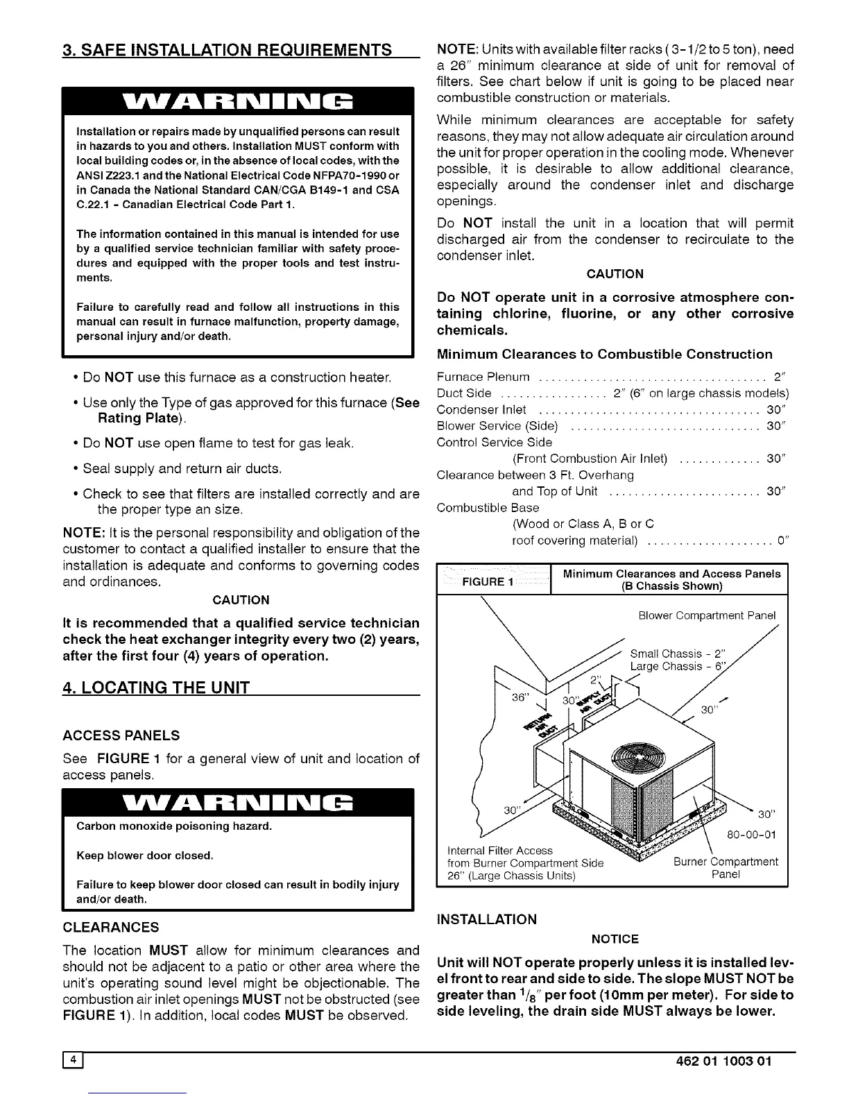
See FIGURE 1 for a general view of unit and location of
access panels.
Carbon monoxide poisoning hazard.
Keep blower door closed.
Failure to keep blower door closed can result in bodily injury
and/or death.
CLEARANCES
The location MUST allow for minimum clearances and
should not be adjacent to a patio or other area where the
unit's operating sound level might be objectionable. The
combustion air inlet openings MUST not be obstructed (see
FIGURE 1). In addition, local codes MUST be observed.
NOTE: Units with available filter racks ( 3-1/2 to 5 ton), need
a 26" minimum clearance at side of unit for removal of
filters. See chart below if unit is going to be placed near
combustible construction or materials.
While minimum clearances are acceptable for safety
reasons, they may not allow adequate air circulation around
the unit for proper operation in the cooling mode. Whenever
possible, it is desirable to allow additional clearance,
especially around the condenser inlet and discharge
openings.
Do NOT install the unit in a location that will permit
discharged air from the condenser to recirculate to the
condenser inlet.
CAUTION
Do NOT operate unit in a corrosive atmosphere con-
taining chlorine, fluorine, or any other corrosive
chemicals.
Minimum Clearances to Combustible Construction
Furnace Plenum .................................... 2"
Duct Side ................. 2" (6" on large chassis models)
Condenser Inlet ................................... 30"
Blower Service (Side) .............................. 30"
Control Service Side
(Front Combustion Air Inlet) ............. 30"
Clearance between 3 Ft. Overhang
and Top of Unit ........................ 30"
Combustible Base
(Wood or Class A, B or C
roof covering material) .................... 0"
FIGURE i Minimum Clearances(BChassisandshown)ACcessPanels
Blower Compartment Panel
Large Chassis
Internal Filter Access
from Burner Compartment Side
26" (Large Chassis Units)
80 _
80-00-01
Burner Compartment
Panel
INSTALLATION
NOTICE
Unit will NOT operate properly unless it is installed lev-
el front to rear and side to side. The slope MUST NOT be
greater than 1/8"per foot (10mm per meter). For side to
side leveling, the drain side MUST always be lower.
141 462 01 1003 01