Ground Level Installation
Ground level platform requirements:
- The unit MUST be situated to provide safe access for
servicing.
Platform may be made of either concrete or pressure
treated wood and MUST be level and strong enough to
support unit weight.
Position platform separate from building foundation.
Install in well-drained area, with top surface of platform
above grade level.
Platform must be high enough to allow for proper con-
densate trap installation and drainage. See FIGURE 3
and associated text for more information about conden-
sate drainage.
Rooftop Installation
Rooftop platform requirements:
- The unit MUST be situated to provide safe access for
servicing.
- The existing roof structure MUST be adequate to sup-
port the weight of the unit or the roof MUST be
reinforced.
Check the weight of the unit in relation to the roof struc-
ture and local building codes or ordinances and
reinforce roof structure if necessary. See the last page
of this manual for unit weights.
- Support for the unit MUST be level and strong enough
to carry unit weight. The support may consist of a plat-
form or a combination of platform and roof beams or
curb.
- See Hoisting section for hoisting instructions.
HOISTING
NOTE: All access panels MUST be secured in place before
hoisting.
The unit should be hoisted with two lifting slings. Attach the
slings to rigging shackles that have been hooked through
holes in the base rail.
Two spreader bars MUST be placed on top of the unit to
protect the unit from damage from the pressure exerted by
the slings. Make sure that all equipment is adequate to
handle the weight of the unit and that the slings will not allow
the unit to shift.
Refer to FIGURE 17 on the back cover of this manual for
illustrated rigging instructions and weight chart.
DOWNFLOW CONVERSION
NOTE: In downflow applications with roof curbs or jack
stands, the center rail under the unit must be removed. The
center rail is attached to the base rail with screws.
These units are adaptable to downflow use. To convert to
downflow use, follow these steps:
1. Remove the blockoff plates found in the return air
compartment and the supply air compartment.
NOTE: Blockoff plate in the supply air compartment only
contains one screw. If reinstalling plate, back part of plate
MUST fit into mating dimples on flange. To reinstall, slant
plate into dimples, then put plate into position and fasten
with screw.
2. Install the removed plates on the horizontal return and
supply air openings.
3. Install roof curb on the building. Be sure to follow all di-
rections included with curb and all applicable building
codes in your installation.
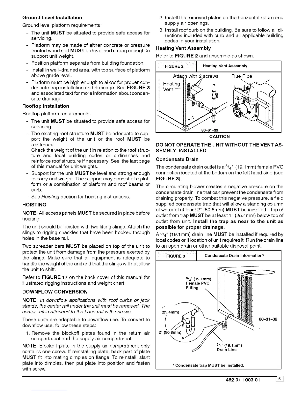
Heating Vent Assembly
Refer to FIGURE 2 and assemble as shown.
FIGURE 2 Heating Vent Assembly
Atta(_t?with 2 screws
Heen_ingi__ _
Flue Pipe
CAUTION
DO NOT OPERATE THE UNIT WITHOUT THE VENT AS-
SEMBLY INSTALLED
Condensate Drain
The condensate drain outlet is a 3/4" (19.1 mm) female PVC
connection located at the bottom on the left hand side (see
FIGURE 3).
The circulating blower creates a negative pressure on the
condensate drain line that can prevent the condensate from
draining properly. To combat this negative pressure, a field
supplied condensate trap that will allow a standing column
of water of at least 2" (50.8mm) MUST be installed. Top of
outlet from trap MUST be at least 1" (25.4mm) below top of
outlet from unit. Install the trap as near to the unit as
possible for proper drainage,
A3/4" (19.1mm) drain line MUST be installed if required by
local codes or if location of unit requires it. Run the drain line
to an open drain or other suitable disposal point.
3 | Condensateora ninformation*
$
(25.4mm)
(
2" (50.8mm)
3/4" (19,1mm)
Female PVC
Fitting X
3/4" (19.1mm)
Drain Line
80-31-32
* Condensate trap MUST be installed.
462 01 1003 01 151